How to Use 8 Core 16awg Wire: Examples, Pinouts, and Specs
Introduction
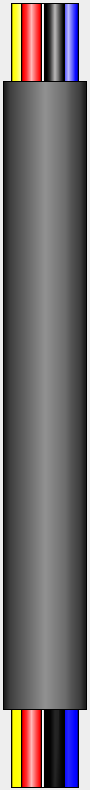
The 8 Core 16AWG Wire is a multi-stranded cable consisting of 8 individual conductors, each with a gauge size of 16 AWG (American Wire Gauge). This wire is designed for low-voltage applications and is widely used in electronics, automotive, and industrial projects. Its flexibility and durability make it ideal for environments requiring frequent movement or bending.
Explore Projects Built with 8 Core 16awg Wire


Explore Projects Built with 8 Core 16awg Wire
Common Applications and Use Cases
- Electronics Projects: Used for connecting multiple components in circuits.
- Automotive Wiring: Suitable for low-voltage power distribution in vehicles.
- Industrial Control Systems: Ideal for signal transmission and power delivery.
- Home Automation: Used in smart home systems for connecting sensors and actuators.
- Audio Systems: Provides reliable connections for speakers and other audio equipment.
Technical Specifications
The following table outlines the key technical details of the 8 Core 16AWG Wire:
| Parameter | Specification |
|---|---|
| Number of Conductors | 8 |
| Conductor Gauge | 16 AWG |
| Conductor Material | Stranded copper |
| Insulation Material | PVC (Polyvinyl Chloride) |
| Voltage Rating | Up to 600V |
| Current Rating | Approximately 22A per conductor (varies by application) |
| Temperature Range | -20°C to 80°C |
| Outer Diameter | ~12-14 mm (varies by insulation thickness) |
| Color Coding | Typically includes 8 distinct colors for easy identification |
Color Coding (Example)
The wire typically comes with the following color-coded insulation for easy identification of individual conductors:
| Conductor Number | Color |
|---|---|
| 1 | Black |
| 2 | Red |
| 3 | White |
| 4 | Green |
| 5 | Blue |
| 6 | Yellow |
| 7 | Brown |
| 8 | Orange |
Usage Instructions
How to Use the 8 Core 16AWG Wire in a Circuit
- Identify the Conductors: Use the color-coded insulation to identify each conductor.
- Strip the Insulation: Use a wire stripper to remove the insulation from the ends of the conductors. Be careful not to damage the copper strands.
- Connect to Components: Solder or use connectors to attach the conductors to your circuit components.
- Secure the Wire: Use cable ties or clamps to secure the wire and prevent strain on the connections.
- Test the Circuit: Verify all connections before powering the circuit to ensure proper functionality.
Important Considerations and Best Practices
- Current Capacity: Ensure the current through each conductor does not exceed its rated capacity (approximately 22A for 16AWG).
- Voltage Rating: Do not exceed the wire's voltage rating of 600V.
- Bend Radius: Avoid sharp bends to prevent damage to the insulation or conductors.
- Environmental Conditions: Use the wire within its specified temperature range (-20°C to 80°C).
- Signal Interference: For signal transmission, consider shielding or twisting pairs of conductors to reduce electromagnetic interference (EMI).
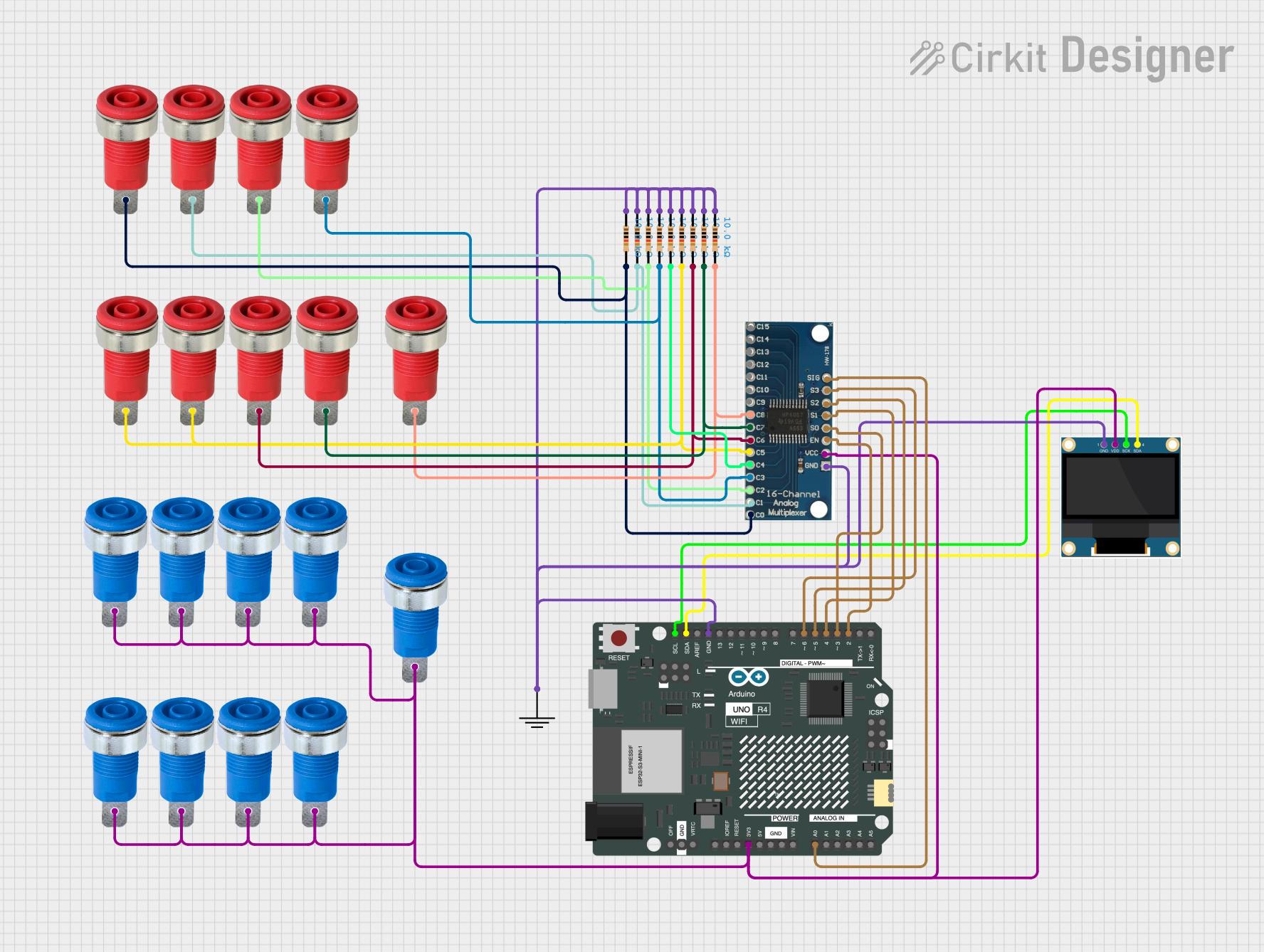
Example: Connecting to an Arduino UNO
The 8 Core 16AWG Wire can be used to connect multiple sensors or actuators to an Arduino UNO. Below is an example of connecting two sensors using this wire:
Circuit Diagram
- Black Wire: Ground (GND)
- Red Wire: 5V Power
- White Wire: Signal for Sensor 1
- Green Wire: Signal for Sensor 2
Arduino Code Example
// Example code for reading two sensors connected via 8 Core 16AWG Wire

const int sensor1Pin = A0; // White wire connected to analog pin A0
const int sensor2Pin = A1; // Green wire connected to analog pin A1

void setup() {
  Serial.begin(9600); // Initialize serial communication
  pinMode(sensor1Pin, INPUT); // Set sensor 1 pin as input
  pinMode(sensor2Pin, INPUT); // Set sensor 2 pin as input
}

void loop() {
  int sensor1Value = analogRead(sensor1Pin); // Read value from sensor 1
  int sensor2Value = analogRead(sensor2Pin); // Read value from sensor 2

  // Print sensor values to the Serial Monitor
  Serial.print("Sensor 1 Value: ");
  Serial.println(sensor1Value);
  Serial.print("Sensor 2 Value: ");
  Serial.println(sensor2Value);

  delay(1000); // Wait for 1 second before reading again
}
Troubleshooting and FAQs
Common Issues
Intermittent Connections:
- Cause: Poor soldering or loose connectors.
- Solution: Re-solder connections or use secure connectors.
Overheating:
- Cause: Exceeding the current rating of the wire.
- Solution: Reduce the current load or use a thicker wire.
Signal Interference:
- Cause: Electromagnetic interference from nearby devices.
- Solution: Use shielded cables or twist signal and ground wires together.
Damaged Insulation:
- Cause: Excessive bending or exposure to sharp objects.
- Solution: Replace the damaged section and avoid sharp bends.
FAQs
Q: Can this wire be used for high-voltage applications?
A: No, the wire is rated for low-voltage applications up to 600V. For high-voltage applications, use a wire with appropriate insulation and voltage rating.
Q: Is the wire suitable for outdoor use?
A: The PVC insulation provides some protection, but for prolonged outdoor use, consider additional weatherproofing or using a wire with UV-resistant insulation.
Q: Can I use this wire for AC power?
A: Yes, it can be used for low-voltage AC power applications, provided the current and voltage ratings are not exceeded.
Q: How do I prevent the wire from fraying?
A: Use heat shrink tubing or electrical tape to secure the ends after stripping the insulation.