Cirkit Designer Logo
Cirkit Designer
Your all-in-one circuit design IDE
Home / 
Component Documentation

How to Use RC 27mhz Receiver: Examples, Pinouts, and Specs

Image of RC 27mhz Receiver
Cirkit Designer LogoDesign with RC 27mhz Receiver in Cirkit Designer

Introduction

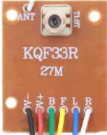
The RC 27MHz Receiver is a radio frequency receiver that operates at 27 MHz. It is commonly used in remote control systems to receive signals from a transmitter. This component is essential in applications such as remote-controlled cars, boats, and other hobbyist projects where wireless communication is required.

Explore Projects Built with RC 27mhz Receiver

Use Cirkit Designer to design, explore, and prototype these projects online. Some projects support real-time simulation. Click "Open Project" to start designing instantly!
Arduino Pro Mini FM Radio with LCD Display and Battery Power
Image of DIY FM Radio RDA5807M V2: A project utilizing RC 27mhz Receiver in a practical application
This circuit is a portable FM radio receiver with an integrated display and audio output. It uses an Arduino Pro Mini to control an RDA5807M FM receiver module, an ADS1115 ADC for additional analog inputs, and a PAM8403 amplifier to drive loudspeakers. The circuit also includes a rotary encoder for user input, an LCD screen for displaying information, and a boost converter for power management.
Cirkit Designer LogoOpen Project in Cirkit Designer
Arduino UNO with 433MHz RF Module for Wireless Communication
Image of Receiver: A project utilizing RC 27mhz Receiver in a practical application
This circuit consists of an Arduino UNO connected to an RXN433MHz radio frequency module. The Arduino provides 5V power and ground to the RF module and is configured to communicate with it via digital pin D11. Additionally, a multimeter is connected with alligator clip cables to measure the voltage supplied to the RF module.
Cirkit Designer LogoOpen Project in Cirkit Designer
433 MHz RF Transmitter and Receiver with Arduino UNO for Wireless Communication
Image of Wireless Communication: A project utilizing RC 27mhz Receiver in a practical application
This circuit consists of two Arduino UNO microcontrollers, each connected to an RF 433 MHz Transmitter and a 433 MHz RF Receiver Module. The setup allows for wireless communication between the two Arduinos, enabling them to send and receive data over a 433 MHz RF link.
Cirkit Designer LogoOpen Project in Cirkit Designer
Arduino-Based Doppler Radar with RF Transmission and LCD Display
Image of Doppler Radar: A project utilizing RC 27mhz Receiver in a practical application
This circuit features an Arduino UNO microcontroller interfaced with an RF 433 MHz Transmitter, a Transmitter RF Module, an LCD screen with I2C communication, and a doppler radar sensor. The Arduino controls the RF transmission and processes the doppler radar's signal, likely for motion detection purposes. The LCD screen is used to display information or statuses, and the RF modules enable wireless communication, possibly to transmit the processed radar data.
Cirkit Designer LogoOpen Project in Cirkit Designer

Explore Projects Built with RC 27mhz Receiver

Use Cirkit Designer to design, explore, and prototype these projects online. Some projects support real-time simulation. Click "Open Project" to start designing instantly!
Image of DIY FM Radio RDA5807M V2: A project utilizing RC 27mhz Receiver in a practical application
Arduino Pro Mini FM Radio with LCD Display and Battery Power
This circuit is a portable FM radio receiver with an integrated display and audio output. It uses an Arduino Pro Mini to control an RDA5807M FM receiver module, an ADS1115 ADC for additional analog inputs, and a PAM8403 amplifier to drive loudspeakers. The circuit also includes a rotary encoder for user input, an LCD screen for displaying information, and a boost converter for power management.
Cirkit Designer LogoOpen Project in Cirkit Designer
Image of Receiver: A project utilizing RC 27mhz Receiver in a practical application
Arduino UNO with 433MHz RF Module for Wireless Communication
This circuit consists of an Arduino UNO connected to an RXN433MHz radio frequency module. The Arduino provides 5V power and ground to the RF module and is configured to communicate with it via digital pin D11. Additionally, a multimeter is connected with alligator clip cables to measure the voltage supplied to the RF module.
Cirkit Designer LogoOpen Project in Cirkit Designer
Image of Wireless Communication: A project utilizing RC 27mhz Receiver in a practical application
433 MHz RF Transmitter and Receiver with Arduino UNO for Wireless Communication
This circuit consists of two Arduino UNO microcontrollers, each connected to an RF 433 MHz Transmitter and a 433 MHz RF Receiver Module. The setup allows for wireless communication between the two Arduinos, enabling them to send and receive data over a 433 MHz RF link.
Cirkit Designer LogoOpen Project in Cirkit Designer
Image of Doppler Radar: A project utilizing RC 27mhz Receiver in a practical application
Arduino-Based Doppler Radar with RF Transmission and LCD Display
This circuit features an Arduino UNO microcontroller interfaced with an RF 433 MHz Transmitter, a Transmitter RF Module, an LCD screen with I2C communication, and a doppler radar sensor. The Arduino controls the RF transmission and processes the doppler radar's signal, likely for motion detection purposes. The LCD screen is used to display information or statuses, and the RF modules enable wireless communication, possibly to transmit the processed radar data.
Cirkit Designer LogoOpen Project in Cirkit Designer

Technical Specifications

Key Technical Details

Parameter Value
Operating Frequency 27 MHz
Voltage Range 4.5V - 6V
Current Consumption 10mA - 20mA
Sensitivity -105 dBm
Modulation Type AM (Amplitude Modulation)
Output Type Digital

Pin Configuration and Descriptions

Pin Number Pin Name Description
1 VCC Power supply (4.5V - 6V)
2 GND Ground
3 DATA Digital output signal
4 ANT Antenna connection

Usage Instructions

How to Use the Component in a Circuit

  1. Power Supply: Connect the VCC pin to a 4.5V - 6V power supply. Ensure that the power supply is stable and within the specified range to avoid damaging the receiver.
  2. Ground Connection: Connect the GND pin to the ground of your circuit.
  3. Data Output: The DATA pin provides the digital output signal received from the transmitter. This pin can be connected to a microcontroller or any other digital input device.
  4. Antenna: Connect an appropriate antenna to the ANT pin to ensure proper reception of the 27 MHz signal.

Important Considerations and Best Practices

  • Antenna Placement: Ensure that the antenna is placed in an open area, away from any metal objects or other sources of interference.
  • Power Supply: Use a regulated power supply to avoid voltage fluctuations that could affect the receiver's performance.
  • Signal Interference: Be aware of other devices operating at the same frequency (27 MHz) that could cause interference.

Example Circuit with Arduino UNO

Below is an example of how to connect the RC 27MHz Receiver to an Arduino UNO:

// Pin definitions
const int dataPin = 2; // Connect DATA pin of the receiver to digital pin 2

void setup() {
  Serial.begin(9600); // Initialize serial communication at 9600 baud rate
  pinMode(dataPin, INPUT); // Set dataPin as an input
}

void loop() {
  int receivedSignal = digitalRead(dataPin); // Read the signal from the receiver
  Serial.println(receivedSignal); // Print the received signal to the Serial Monitor
  delay(100); // Small delay to avoid flooding the Serial Monitor
}

Troubleshooting and FAQs

Common Issues Users Might Face

  1. No Signal Reception:

    • Solution: Check the antenna connection and ensure it is properly placed. Verify that the transmitter is functioning correctly and within range.
  2. Intermittent Signal:

    • Solution: Ensure that there are no sources of interference nearby. Check the power supply for stability and proper voltage.
  3. Incorrect Data Output:

    • Solution: Verify the connections between the receiver and the microcontroller. Ensure that the data pin is correctly configured as an input.

FAQs

Q1: Can I use a different frequency transmitter with this receiver?

  • A1: No, the RC 27MHz Receiver is specifically designed to operate at 27 MHz. Using a different frequency transmitter will not work.

Q2: What type of antenna should I use?

  • A2: A simple wire antenna of approximately 1 meter in length is usually sufficient for most applications. Ensure that the antenna is placed in an open area for optimal reception.

Q3: Can I use this receiver with a 3.3V microcontroller?

  • A3: The receiver requires a power supply of 4.5V - 6V. However, the data output can be interfaced with a 3.3V microcontroller using a level shifter or voltage divider.

By following this documentation, users should be able to effectively integrate the RC 27MHz Receiver into their projects, ensuring reliable wireless communication.