Cirkit Designer
Your all-in-one circuit design IDE
Home /
Component Documentation
How to Use QTR-8A Reflectance Sensor Array: Examples, Pinouts, and Specs
Introduction
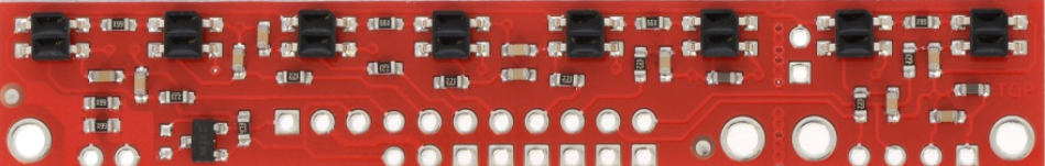
The QTR-8A Reflectance Sensor Array by Pololu is an array of 8 reflectance sensors designed for line following and edge detection in robotics. Each sensor in the array provides an analog output that corresponds to the reflectance of the surface beneath it. This makes the QTR-8A ideal for applications such as line-following robots, edge detection, and other robotics projects that require surface reflectance measurements.
Explore Projects Built with QTR-8A Reflectance Sensor Array
Arduino Nano-Powered PID Line Following Robot with Reflectance Sensor Array and Dual Motor Driver
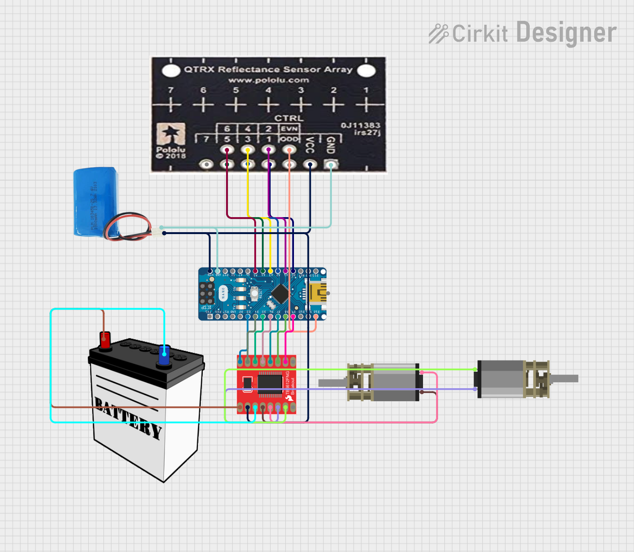
This circuit is designed for an advanced line-following robot that uses a QTRX-HD-07RC Reflectance Sensor Array for line sensing and a Motor Driver 1A Dual TB6612FNG to control two DC Mini Metal Gear Motors. The Arduino Nano serves as the microcontroller, running a PID control algorithm to adjust the motor speeds for precise tracking. Power is supplied by a 5V battery for the logic and a 12V battery for the motor driver.
Arduino-Controlled Robotics Platform with Reflectance Sensor Array and Ultrasonic Obstacle Detection
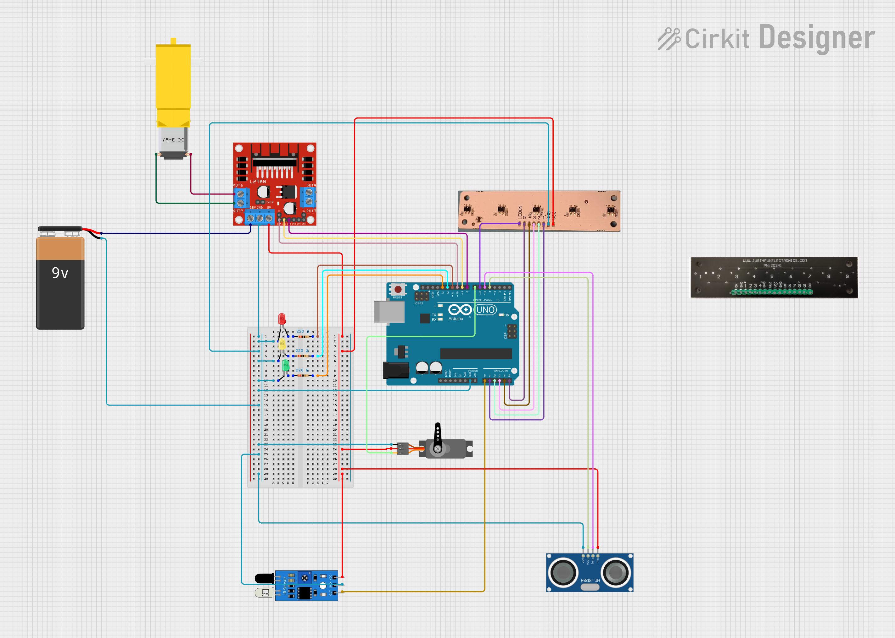
This is a robotic control system utilizing an Arduino UNO to interface with a DC gearmotor via an L298N motor driver for motion control, a servo motor for additional actuation, and multiple sensors (IR, ultrasonic, reflectance sensor array) for environmental sensing. It also includes RGB status LEDs with current-limiting resistors. The embedded code for the Arduino is currently a placeholder, requiring further development for specific functionalities.
Arduino UNO-Based Autonomous Robot with Reflectance and Ultrasonic Sensors
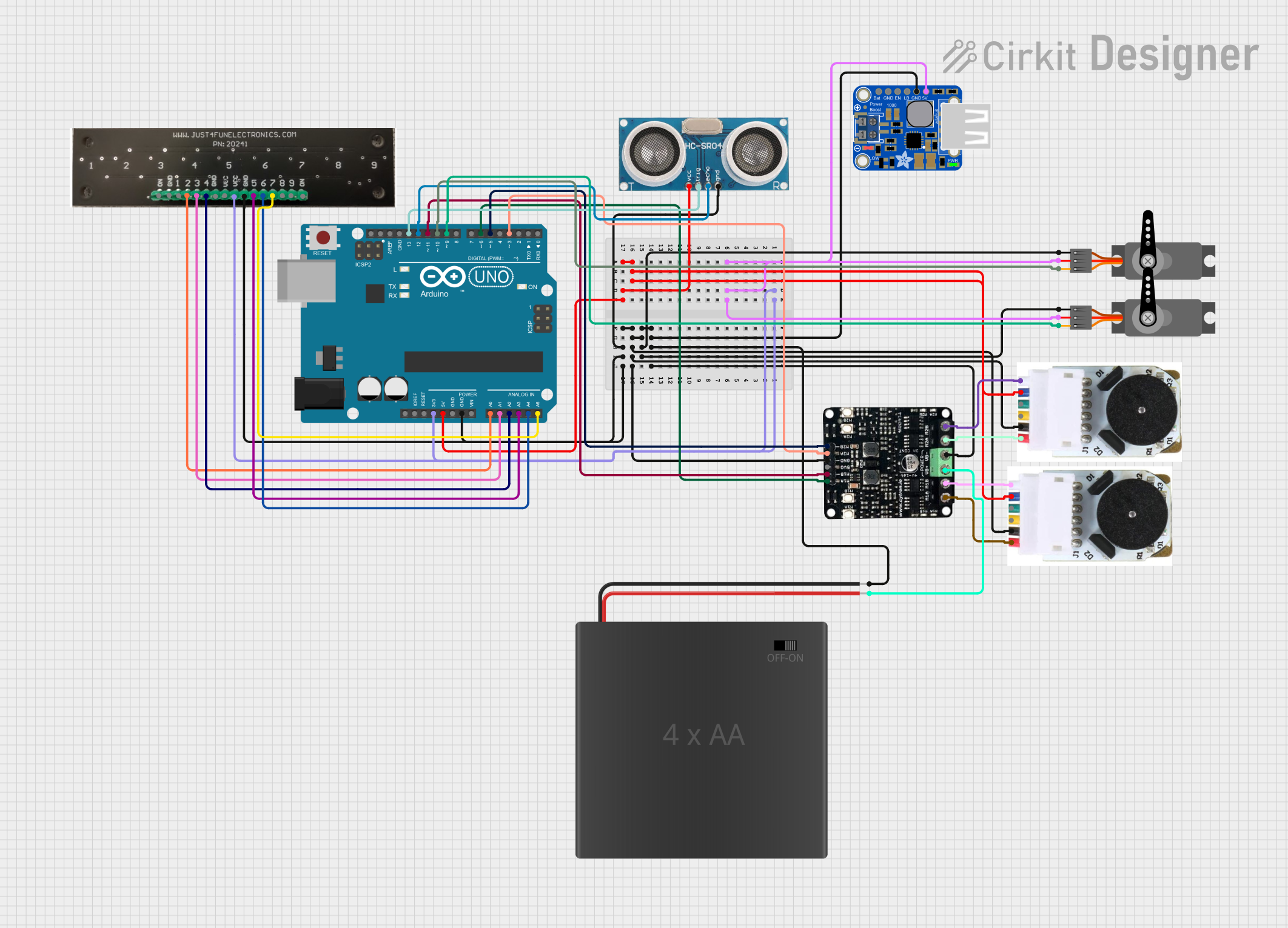
This circuit is a robotic system controlled by an Arduino UNO, featuring a reflectance sensor array for line detection, an ultrasonic sensor for distance measurement, and two DC motors with encoders for movement. It also includes two servos for additional mechanical control, all powered by a PowerBoost 1000 Basic Terminal USB and a 4xAA battery pack.
ESP32-Based Environmental Monitoring System with Gas Sensors and OLED Display
This circuit is an environmental monitoring system using an ESP32 microcontroller. It integrates various sensors, including the MQ-7 and MQ135 gas sensors, ENS160+AHT21 air quality and temperature/humidity sensor, and a KY-037 microphone, to collect environmental data. The data is displayed on a 1.3" OLED screen.
Explore Projects Built with QTR-8A Reflectance Sensor Array
Arduino Nano-Powered PID Line Following Robot with Reflectance Sensor Array and Dual Motor Driver
This circuit is designed for an advanced line-following robot that uses a QTRX-HD-07RC Reflectance Sensor Array for line sensing and a Motor Driver 1A Dual TB6612FNG to control two DC Mini Metal Gear Motors. The Arduino Nano serves as the microcontroller, running a PID control algorithm to adjust the motor speeds for precise tracking. Power is supplied by a 5V battery for the logic and a 12V battery for the motor driver.
Arduino-Controlled Robotics Platform with Reflectance Sensor Array and Ultrasonic Obstacle Detection
This is a robotic control system utilizing an Arduino UNO to interface with a DC gearmotor via an L298N motor driver for motion control, a servo motor for additional actuation, and multiple sensors (IR, ultrasonic, reflectance sensor array) for environmental sensing. It also includes RGB status LEDs with current-limiting resistors. The embedded code for the Arduino is currently a placeholder, requiring further development for specific functionalities.
Arduino UNO-Based Autonomous Robot with Reflectance and Ultrasonic Sensors
This circuit is a robotic system controlled by an Arduino UNO, featuring a reflectance sensor array for line detection, an ultrasonic sensor for distance measurement, and two DC motors with encoders for movement. It also includes two servos for additional mechanical control, all powered by a PowerBoost 1000 Basic Terminal USB and a 4xAA battery pack.
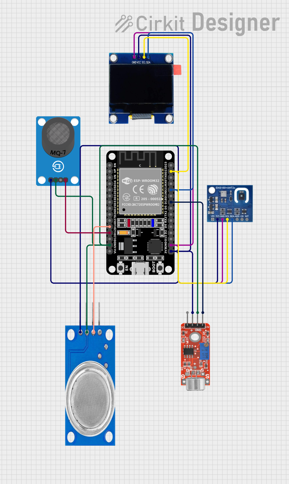
ESP32-Based Environmental Monitoring System with Gas Sensors and OLED Display
This circuit is an environmental monitoring system using an ESP32 microcontroller. It integrates various sensors, including the MQ-7 and MQ135 gas sensors, ENS160+AHT21 air quality and temperature/humidity sensor, and a KY-037 microphone, to collect environmental data. The data is displayed on a 1.3" OLED screen.
Technical Specifications
Key Technical Details
- Manufacturer: Pololu
- Part ID: QTR-8A
- Number of Sensors: 8
- Operating Voltage: 3.3V to 5V
- Current Consumption: 100 mA (typical)
- Output Type: Analog
- Sensor Type: Infrared reflectance sensor
- Dimensions: 75mm x 10mm x 3mm
- Weight: 3.09g
Pin Configuration and Descriptions
| Pin | Name | Description |
|---|---|---|
| 1 | VCC | Power supply (3.3V to 5V) |
| 2 | GND | Ground |
| 3 | OUT0 | Analog output from sensor 0 |
| 4 | OUT1 | Analog output from sensor 1 |
| 5 | OUT2 | Analog output from sensor 2 |
| 6 | OUT3 | Analog output from sensor 3 |
| 7 | OUT4 | Analog output from sensor 4 |
| 8 | OUT5 | Analog output from sensor 5 |
| 9 | OUT6 | Analog output from sensor 6 |
| 10 | OUT7 | Analog output from sensor 7 |
| 11 | LEDON | Control pin for turning the IR LEDs on and off (active low) |
Usage Instructions
How to Use the Component in a Circuit
- Power Supply: Connect the VCC pin to a 3.3V or 5V power supply and the GND pin to the ground of your circuit.
- Analog Outputs: Connect the OUT0 to OUT7 pins to the analog input pins of your microcontroller (e.g., Arduino).
- LED Control: Connect the LEDON pin to a digital output pin of your microcontroller to control the IR LEDs. Pulling this pin low will turn the LEDs on.
Example Circuit with Arduino UNO
- VCC -> 5V (Arduino)
- GND -> GND (Arduino)
- OUT0 -> A0 (Arduino)
- OUT1 -> A1 (Arduino)
- OUT2 -> A2 (Arduino)
- OUT3 -> A3 (Arduino)
- OUT4 -> A4 (Arduino)
- OUT5 -> A5 (Arduino)
- OUT6 -> A6 (Arduino)
- OUT7 -> A7 (Arduino)
- LEDON -> D2 (Arduino)
Important Considerations and Best Practices
- Power Supply: Ensure that the power supply voltage matches the operating voltage range of the sensor array (3.3V to 5V).
- Analog Readings: Use the
analogRead()function in Arduino to read the analog values from the sensor outputs. - LED Control: Use a digital pin to control the LEDON pin. Pulling it low will turn the IR LEDs on, which is necessary for the sensors to function correctly.
Sample Arduino Code
// Define the pins for the sensor outputs and LED control
const int sensorPins[8] = {A0, A1, A2, A3, A4, A5, A6, A7};
const int ledPin = 2;

void setup() {
  // Initialize serial communication for debugging
  Serial.begin(9600);

  // Set the LED control pin as output
  pinMode(ledPin, OUTPUT);

  // Turn on the IR LEDs
  digitalWrite(ledPin, LOW);
}

void loop() {
  // Read and print the sensor values
  for (int i = 0; i < 8; i++) {
    int sensorValue = analogRead(sensorPins[i]);
    Serial.print("Sensor ");
    Serial.print(i);
    Serial.print(": ");
    Serial.println(sensorValue);
  }

  // Add a small delay to avoid flooding the serial monitor
  delay(100);
}
Troubleshooting and FAQs
Common Issues Users Might Face
No Output from Sensors:
- Solution: Ensure that the VCC and GND pins are connected correctly. Check if the LEDON pin is pulled low to turn on the IR LEDs.
Inconsistent Readings:
- Solution: Ensure that the sensor array is positioned correctly over the surface. Check for any obstructions or reflective surfaces that might interfere with the readings.
High Power Consumption:
- Solution: Verify that the power supply can provide sufficient current (100 mA typical). If using a battery, ensure it is fully charged.
Solutions and Tips for Troubleshooting
- Check Connections: Double-check all connections to ensure they are secure and correct.
- Calibrate Sensors: If readings are inconsistent, consider calibrating the sensors by taking multiple readings and averaging them.
- Use Proper Surfaces: Ensure that the surface being detected is suitable for reflectance measurements (e.g., white lines on a dark background for line following).
By following this documentation, users should be able to effectively integrate and utilize the QTR-8A Reflectance Sensor Array in their robotics projects.