How to Use Modulo Led Infrarrojo Receptor: Examples, Pinouts, and Specs
Introduction
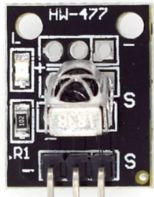
The Modulo Led Infrarrojo Receptor (KY-022) is an infrared receiver module designed to detect and process infrared (IR) signals. Manufactured by Sensor, this module is widely used in remote control applications to receive commands from IR remote control devices. It is compact, easy to use, and compatible with microcontrollers like Arduino, making it ideal for hobbyists and professionals alike.
Explore Projects Built with Modulo Led Infrarrojo Receptor


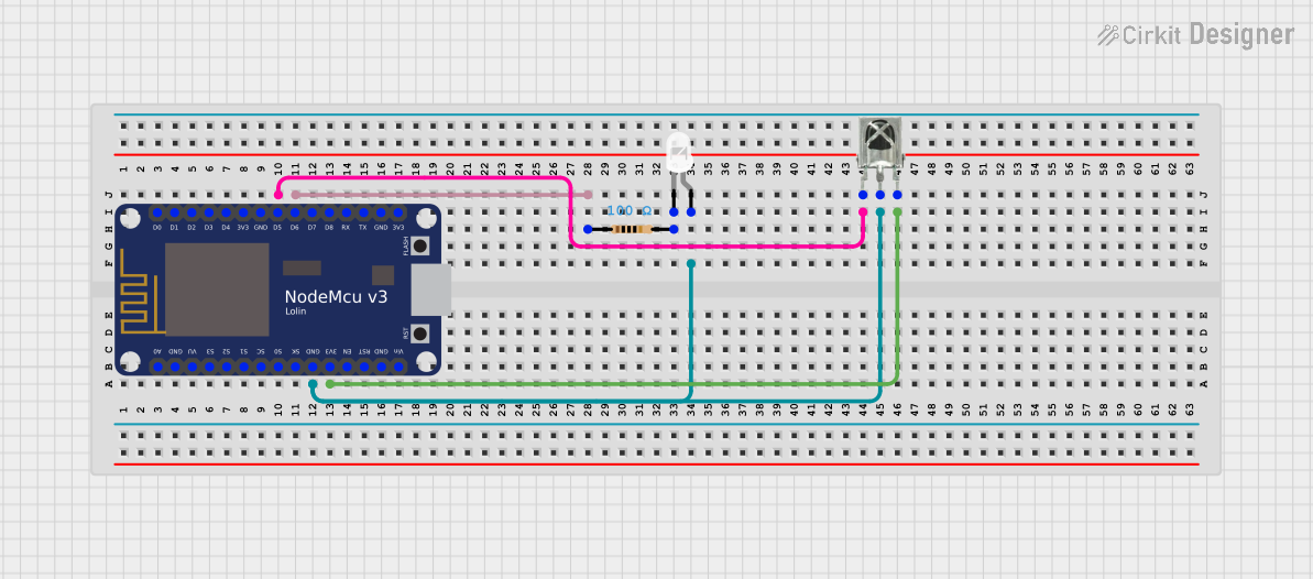
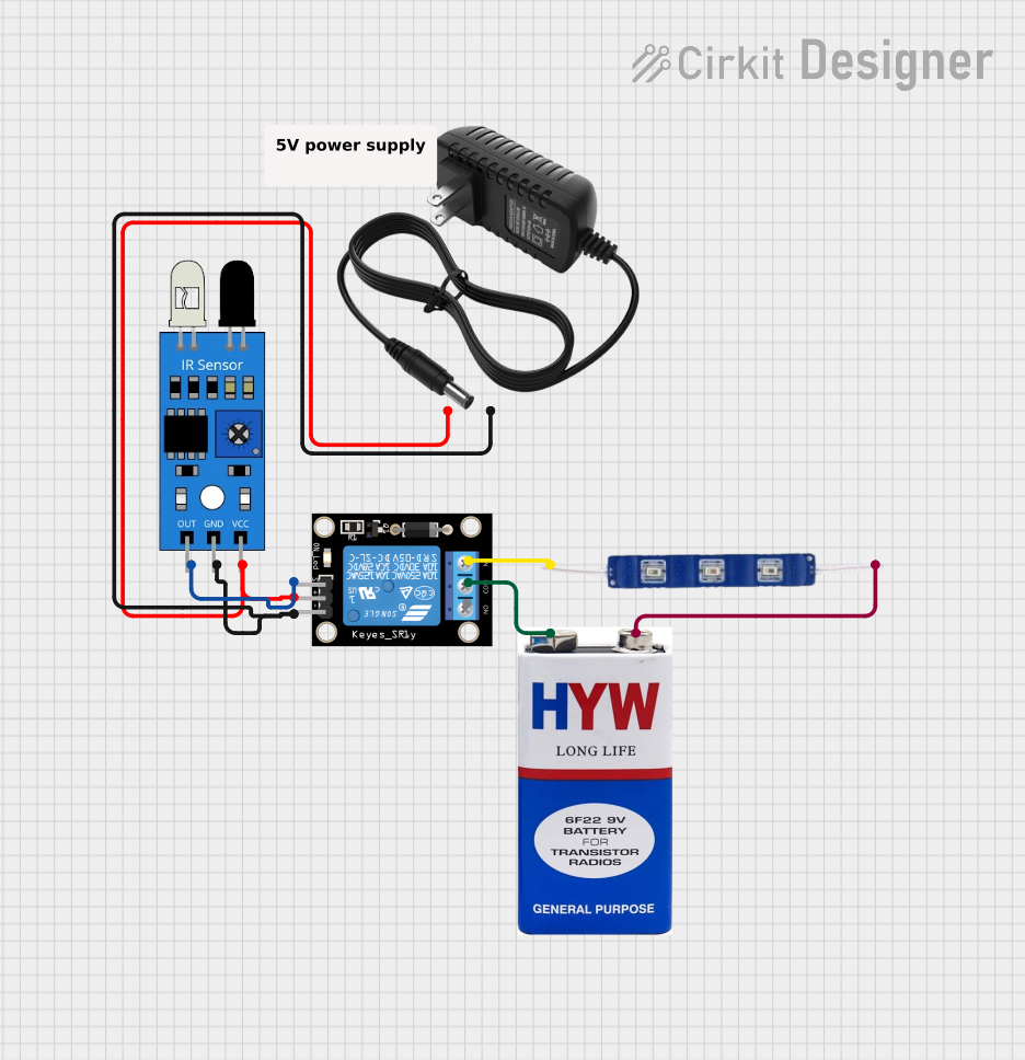
Explore Projects Built with Modulo Led Infrarrojo Receptor
Common Applications and Use Cases
- Remote control signal reception for TVs, air conditioners, and other appliances
- Wireless communication in embedded systems
- IR-based data transmission and reception
- Proximity sensing and object detection
- Robotics and automation projects
Technical Specifications
The following table outlines the key technical details of the KY-022 module:
| Parameter | Specification |
|---|---|
| Operating Voltage | 3.3V to 5V |
| Operating Current | 0.4mA to 1.5mA |
| Carrier Frequency | 38kHz |
| Reception Distance | Up to 18 meters (depending on IR source) |
| Reception Angle | ±45° |
| Output Signal | Digital (active low) |
| Dimensions | 18.5mm x 10mm x 8mm |
Pin Configuration and Descriptions
The KY-022 module has three pins, as described in the table below:
| Pin | Name | Description |
|---|---|---|
| 1 | Signal | Digital output pin that provides the received IR signal. |
| 2 | VCC | Power supply pin (3.3V to 5V). |
| 3 | GND | Ground pin. |
Usage Instructions
How to Use the KY-022 in a Circuit
Connect the Pins:
- Connect the VCC pin to a 3.3V or 5V power supply.
- Connect the GND pin to the ground of your circuit.
- Connect the Signal pin to a digital input pin on your microcontroller (e.g., Arduino).
Place the Module:
- Ensure the module is positioned to face the IR source (e.g., a remote control) for optimal signal reception.
Load the Code:
- If using an Arduino, you can use the
IRremotelibrary to decode the received IR signals.
- If using an Arduino, you can use the
Important Considerations and Best Practices
- Power Supply: Ensure a stable power supply to avoid signal distortion.
- Interference: Avoid placing the module near strong light sources (e.g., sunlight or fluorescent lights) as they may interfere with IR signal reception.
- Distance and Angle: For best results, ensure the IR source is within the module's reception distance and angle.
Example Code for Arduino UNO
Below is an example code to use the KY-022 module with an Arduino UNO to decode IR signals:
#include <IRremote.h> // Include the IRremote library

const int RECV_PIN = 2; // Define the pin connected to the KY-022 Signal pin
IRrecv irrecv(RECV_PIN); // Create an IRrecv object
decode_results results;  // Create a variable to store decoded results

void setup() {
  Serial.begin(9600); // Initialize serial communication
  irrecv.enableIRIn(); // Start the IR receiver
  Serial.println("IR Receiver is ready to receive signals.");
}

void loop() {
  if (irrecv.decode(&results)) { // Check if a signal is received
    Serial.print("Received IR code: ");
    Serial.println(results.value, HEX); // Print the received code in hexadecimal
    irrecv.resume(); // Prepare to receive the next signal
  }
}
Notes on the Code
- Install the
IRremotelibrary in the Arduino IDE before uploading the code. - Connect the Signal pin of the KY-022 to digital pin 2 on the Arduino UNO.
- Open the Serial Monitor (set to 9600 baud) to view the received IR codes.
Troubleshooting and FAQs
Common Issues and Solutions
No Signal Detected:
- Cause: Incorrect wiring or loose connections.
- Solution: Double-check the connections, ensuring the pins are correctly connected to the power supply, ground, and microcontroller.
Interference from Ambient Light:
- Cause: Strong light sources interfering with the IR signal.
- Solution: Shield the module from direct sunlight or fluorescent lights.
Short Reception Distance:
- Cause: Weak IR source or misalignment.
- Solution: Ensure the IR source is within the module's reception range and properly aligned.
Unstable Output:
- Cause: Unstable power supply.
- Solution: Use a regulated power supply to provide consistent voltage.
FAQs
Q1: Can the KY-022 module work with 3.3V microcontrollers?
A1: Yes, the KY-022 is compatible with both 3.3V and 5V systems.
Q2: What is the maximum distance for signal reception?
A2: The module can receive signals from up to 18 meters, depending on the strength of the IR source.
Q3: Can I use the KY-022 to control devices?
A3: No, the KY-022 is a receiver module. To control devices, you would need an IR transmitter module.
Q4: How do I decode the received IR signals?
A4: Use the IRremote library with an Arduino to decode and interpret the received signals.
By following this documentation, you can effectively integrate the KY-022 module into your projects and troubleshoot any issues that arise.