How to Use 2 Gang Outlet: Examples, Pinouts, and Specs
Introduction
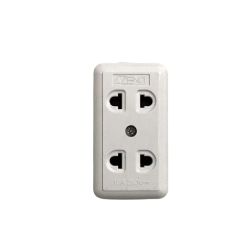
A 2 gang outlet is an electrical receptacle designed to provide two separate sockets within a single wall plate. This component allows for the simultaneous connection of two devices, making it a convenient and efficient solution for powering multiple appliances or electronics in residential, commercial, or industrial settings.
Common applications include:
- Powering household appliances such as lamps, chargers, and small kitchen devices.
- Providing power to office equipment like computers and printers.
- Supporting industrial tools and machinery in workshops or garages.
Explore Projects Built with 2 Gang Outlet


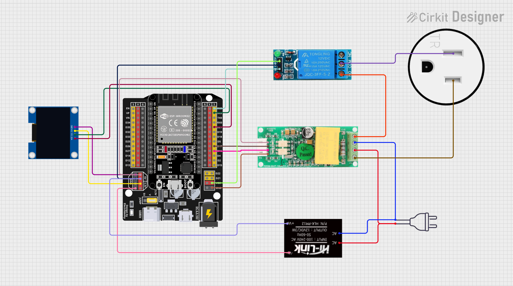

Explore Projects Built with 2 Gang Outlet
Technical Specifications
Below are the key technical details for a standard 2 gang outlet:
| Specification | Details |
|---|---|
| Voltage Rating | 120V AC (North America) or 230V AC (Europe and other regions) |
| Current Rating | 15A or 20A (depending on the model and region) |
| Frequency | 50Hz or 60Hz |
| Material | High-impact thermoplastic or polycarbonate |
| Grounding | Equipped with a grounding terminal for safety |
| Mounting Style | Flush-mounted into a standard electrical box |
| Certifications | UL Listed, CE Mark, or other regional safety certifications |
| Dimensions | Standard wall plate size (e.g., 4.5" x 2.75" in North America) |
| Operating Temperature | -20°C to 60°C |
Pin Configuration and Descriptions
The 2 gang outlet has the following connections:
| Pin/Terminal | Description |
|---|---|
| Line (Hot) | Connects to the live wire supplying power to the outlet. |
| Neutral | Connects to the neutral wire to complete the circuit. |
| Ground | Connects to the ground wire for safety and to prevent electrical shocks. |
Usage Instructions
How to Use the 2 Gang Outlet in a Circuit
- Turn Off Power: Before installation, switch off the power supply at the circuit breaker to avoid electrical hazards.
- Prepare the Electrical Box: Ensure the electrical box is properly installed and has enough space for the 2 gang outlet.
- Connect the Wires:
- Attach the line (hot) wire to the brass terminal.
- Attach the neutral wire to the silver terminal.
- Attach the ground wire to the green terminal.
- Secure the Outlet: Mount the outlet into the electrical box using screws, ensuring it is flush with the wall.
- Attach the Wall Plate: Secure the wall plate over the outlet for a clean finish.
- Restore Power: Turn the circuit breaker back on and test the outlet with a device to ensure proper functionality.
Important Considerations and Best Practices
- Always follow local electrical codes and regulations when installing or replacing outlets.
- Use a voltage tester to confirm that the power is off before handling wires.
- Ensure the outlet's current and voltage ratings match the requirements of your circuit.
- For outdoor or wet locations, use a weatherproof 2 gang outlet with a protective cover.
- If unsure about installation, consult a licensed electrician.
Arduino Integration
While a 2 gang outlet is not directly connected to an Arduino, it can be used in projects involving relays to control AC devices. Below is an example of how to control a 2 gang outlet using a relay module and an Arduino UNO:
/*
  Example: Controlling a 2 Gang Outlet with Arduino and a Relay Module
  This code demonstrates how to turn on/off an outlet using a relay.
  WARNING: Ensure proper isolation between the Arduino and high-voltage AC circuits.
*/

const int relayPin = 7; // Pin connected to the relay module

void setup() {
  pinMode(relayPin, OUTPUT); // Set relay pin as output
  digitalWrite(relayPin, LOW); // Ensure relay is off at startup
}

void loop() {
  digitalWrite(relayPin, HIGH); // Turn on the relay (outlet powered)
  delay(5000); // Keep the outlet on for 5 seconds
  digitalWrite(relayPin, LOW); // Turn off the relay (outlet off)
  delay(5000); // Keep the outlet off for 5 seconds
}
Note: Always use a relay module rated for the voltage and current of the outlet. Ensure proper isolation between the low-voltage Arduino circuit and the high-voltage AC circuit.
Troubleshooting and FAQs
Common Issues and Solutions
Outlet Does Not Work:
- Cause: Loose or incorrect wiring.
- Solution: Double-check all connections, ensuring wires are securely attached to the correct terminals.
Sparks or Burning Smell:
- Cause: Overloaded circuit or damaged outlet.
- Solution: Disconnect power immediately. Inspect the outlet and replace it if damaged. Avoid exceeding the outlet's current rating.
Devices Not Receiving Power:
- Cause: Tripped circuit breaker or blown fuse.
- Solution: Check the circuit breaker or fuse box and reset/replace as needed.
Outlet Feels Warm:
- Cause: High power draw or loose connections.
- Solution: Ensure the outlet is not overloaded. Tighten connections if necessary.
FAQs
Q: Can I install a 2 gang outlet outdoors?
A: Yes, but you must use a weatherproof outlet and enclosure designed for outdoor use.
Q: Can I replace a single gang outlet with a 2 gang outlet?
A: Yes, but you will need to replace the electrical box with a larger one to accommodate the 2 gang outlet.
Q: Is it safe to use a 2 gang outlet for high-power appliances?
A: Yes, as long as the total current draw does not exceed the outlet's rating (e.g., 15A or 20A).
Q: Do I need a ground wire for installation?
A: Yes, grounding is essential for safety and to comply with electrical codes.