
How to Use PHOTOTRANSISTOR REFLECTIVE OBJECT SENSOR: Examples, Pinouts, and Specs
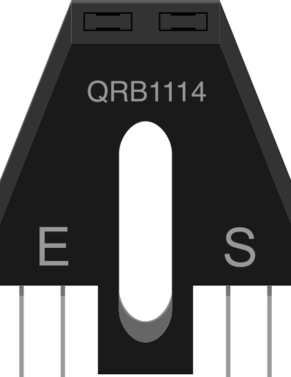
 Design with PHOTOTRANSISTOR REFLECTIVE OBJECT SENSOR in Cirkit Designer
Introduction
A phototransistor reflective object sensor detects the presence of nearby objects by emitting and receiving infrared light. It consists of an infrared LED and a phototransistor housed together. When an object reflects the emitted infrared light back to the phototransistor, the sensor activates, producing an output signal.
This component is widely used in applications such as:
- Obstacle detection in robotics
- Proximity sensing in automation systems
- Line-following robots
- Object counting systems
- Touchless switches
Explore Projects Built with PHOTOTRANSISTOR REFLECTIVE OBJECT SENSOR
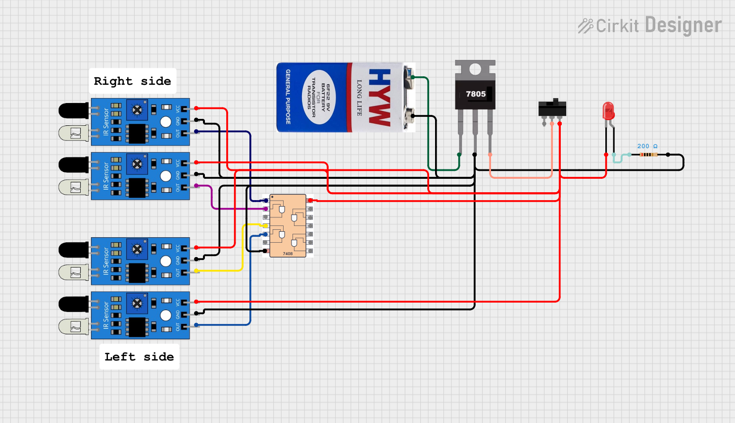 Open Project in Cirkit Designer
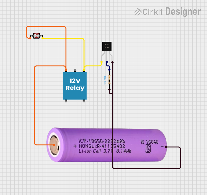 Open Project in Cirkit Designer
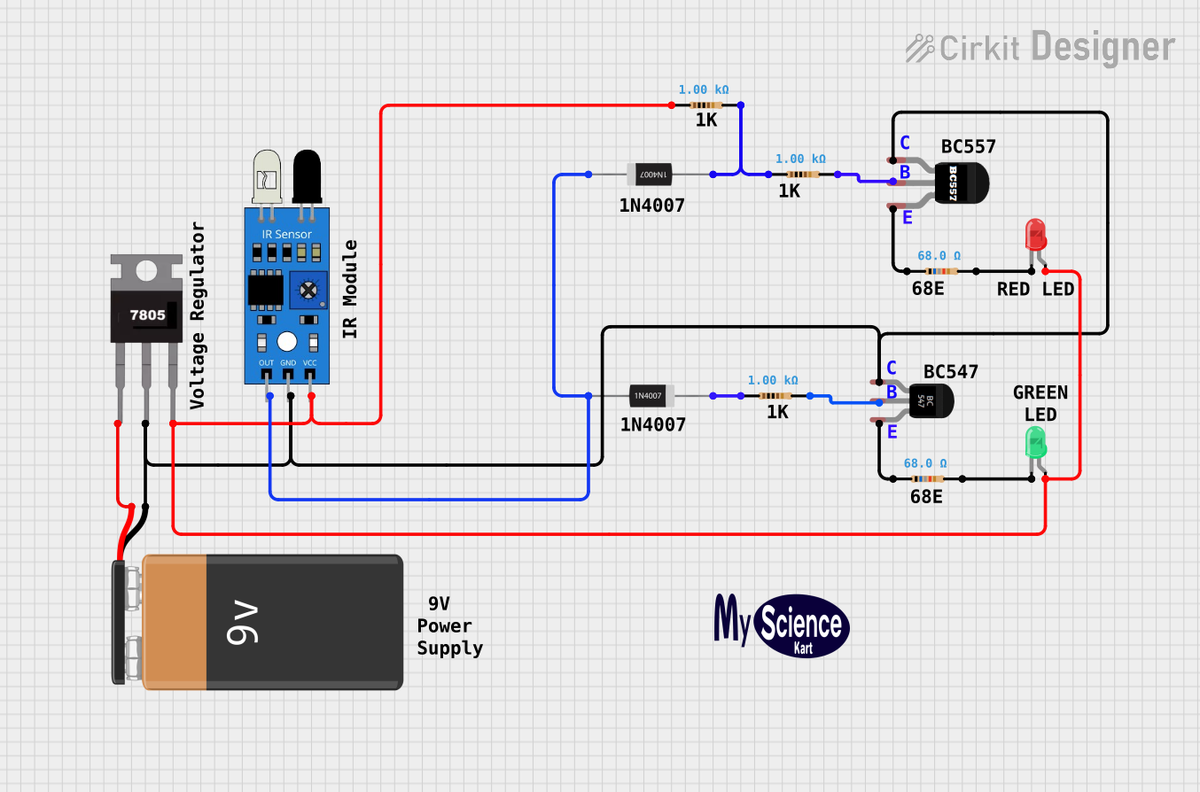 Open Project in Cirkit Designer
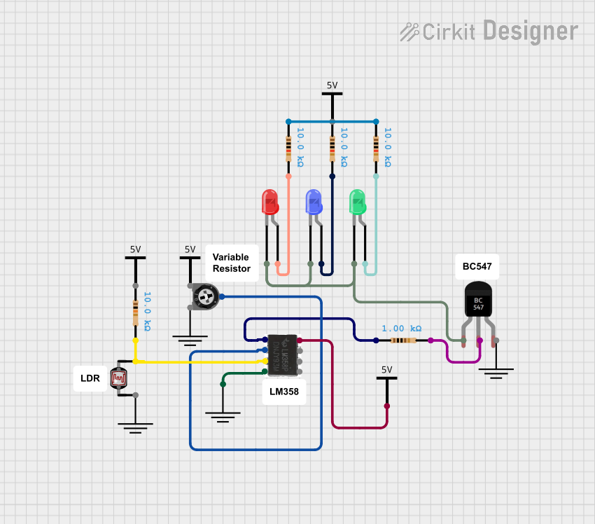 Open Project in Cirkit Designer
Explore Projects Built with PHOTOTRANSISTOR REFLECTIVE OBJECT SENSOR
Open Project in Cirkit DesignerOpen Project in Cirkit DesignerOpen Project in Cirkit DesignerOpen Project in Cirkit DesignerTechnical Specifications
Below are the key technical details of a typical phototransistor reflective object sensor:
| Parameter | Value |
|---|---|
| Operating Voltage | 3.3V to 5V |
| Operating Current | 20mA (typical) |
| Detection Range | 2mm to 15mm (depending on object) |
| Wavelength of IR LED | 940nm |
| Output Type | Analog or Digital (depending on model) |
| Response Time | < 1ms |
| Operating Temperature Range | -25°C to +85°C |
Pin Configuration and Descriptions
The sensor typically has three or four pins. Below is a common pinout configuration:
| Pin | Name | Description |
|---|---|---|
| 1 | VCC | Power supply pin (3.3V to 5V) |
| 2 | GND | Ground connection |
| 3 | OUT | Output signal pin (analog or digital, depending on model) |
| 4 | (Optional) | Some models may include an enable or sensitivity adjustment pin |
Usage Instructions
How to Use the Component in a Circuit
- Power the Sensor: Connect the VCC pin to a 3.3V or 5V power supply and the GND pin to ground.
- Connect the Output: Attach the OUT pin to a microcontroller's input pin (e.g., an analog or digital pin on an Arduino).
- Position the Sensor: Place the sensor so that the object to be detected will pass within its detection range (2mm to 15mm).
- Read the Output: The sensor's output will vary based on the reflected infrared light. For analog sensors, the output voltage will change proportionally to the reflected light intensity. For digital sensors, the output will toggle between HIGH and LOW.
Important Considerations and Best Practices
- Ambient Light Interference: Avoid placing the sensor in direct sunlight or near strong light sources, as this can interfere with its operation.
- Object Reflectivity: The sensor's performance depends on the reflectivity of the object. Highly reflective surfaces (e.g., white or shiny objects) will produce stronger signals.
- Distance Calibration: If the sensor includes a sensitivity adjustment pin or potentiometer, use it to fine-tune the detection range for your application.
- Power Supply Noise: Use decoupling capacitors (e.g., 0.1µF) near the sensor's VCC pin to reduce noise and ensure stable operation.
Example Code for Arduino UNO
Below is an example of how to use a phototransistor reflective object sensor with an Arduino UNO:
// Define the pin connected to the sensor's output
const int sensorPin = A0; // Use an analog pin for analog output sensors
const int ledPin = 13;    // Optional: LED to indicate object detection

void setup() {
  pinMode(sensorPin, INPUT); // Set the sensor pin as input
  pinMode(ledPin, OUTPUT);   // Set the LED pin as output
  Serial.begin(9600);        // Initialize serial communication
}

void loop() {
  int sensorValue = analogRead(sensorPin); // Read the sensor's output value

  // Print the sensor value to the Serial Monitor
  Serial.print("Sensor Value: ");
  Serial.println(sensorValue);

  // If the sensor value exceeds a threshold, turn on the LED
  if (sensorValue > 500) { // Adjust threshold based on your application
    digitalWrite(ledPin, HIGH); // Turn on the LED
  } else {
    digitalWrite(ledPin, LOW);  // Turn off the LED
  }

  delay(100); // Small delay for stability
}
Notes:
- For digital output sensors, replace
analogRead(sensorPin)withdigitalRead(sensorPin)in the code. - Adjust the threshold value (
500in the example) based on the sensor's output and the reflectivity of the object.
Troubleshooting and FAQs
Common Issues and Solutions
Sensor Not Detecting Objects
Cause: The object is outside the detection range.
Solution: Ensure the object is within 2mm to 15mm of the sensor.
Cause: The object is not reflective enough.
Solution: Use objects with higher reflectivity or adjust the sensor's sensitivity (if possible).
Inconsistent Readings
Cause: Ambient light interference.
Solution: Shield the sensor from strong light sources or use it in a controlled environment.
Cause: Electrical noise in the power supply.
Solution: Add a decoupling capacitor (e.g., 0.1µF) near the sensor's VCC pin.
Output Always HIGH or LOW
Cause: Incorrect wiring.
Solution: Double-check the connections, especially the VCC, GND, and OUT pins.
Cause: Faulty sensor.
Solution: Test the sensor with a multimeter or replace it if necessary.
FAQs
Q: Can this sensor detect transparent objects?
A: Transparent objects may not reflect enough infrared light for detection. Use a sensor specifically designed for transparent materials if needed.
Q: How do I increase the detection range?
A: The detection range is limited by the sensor's design. However, you can improve performance by using highly reflective objects or adjusting the sensitivity (if the sensor supports it).
Q: Can I use this sensor with a 3.3V microcontroller?
A: Yes, most phototransistor reflective object sensors operate within a 3.3V to 5V range. Verify the specific sensor's datasheet to confirm compatibility.
Q: Is this sensor suitable for high-speed applications?
A: Yes, with a response time of less than 1ms, this sensor is suitable for high-speed object detection tasks.