
How to Use FT232RQ: Examples, Pinouts, and Specs
 Design with FT232RQ in Cirkit Designer
Introduction
The FT232RQ is a USB to serial converter chip designed to facilitate communication between USB devices and serial devices. It is widely used in microcontroller projects for programming, debugging, and data transfer. This versatile chip simplifies the process of interfacing modern USB ports with legacy serial communication protocols, such as UART.
Explore Projects Built with FT232RQ
 Open Project in Cirkit Designer
 Open Project in Cirkit Designer
 Open Project in Cirkit Designer
 Open Project in Cirkit Designer
Explore Projects Built with FT232RQ
Open Project in Cirkit DesignerOpen Project in Cirkit DesignerOpen Project in Cirkit DesignerOpen Project in Cirkit DesignerCommon Applications and Use Cases
- Programming microcontrollers (e.g., Arduino, PIC, AVR)
- USB-to-serial adapters for legacy devices
- Debugging and monitoring serial communication
- Data logging and transfer between USB and serial devices
- Embedded systems requiring USB connectivity
Technical Specifications
The FT232RQ is a highly integrated chip with robust features for USB-to-serial communication. Below are its key technical specifications:
Key Technical Details
- USB Protocol: USB 2.0 Full Speed (12 Mbps)
- Serial Protocols Supported: UART, RS232, RS422, RS485
- Operating Voltage: 3.3V (core) and 5V (I/O tolerant)
- Data Transfer Rate: Up to 3 Mbps (RS232) or 12 Mbps (RS422/RS485)
- Operating Temperature: -40°C to +85°C
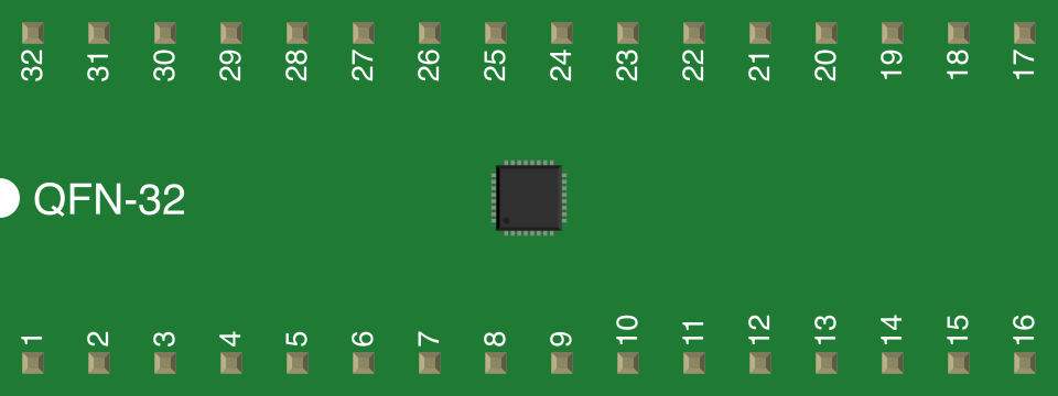
- Package Type: QFN-32 (5mm x 5mm)
- Integrated Features: Internal clock, EEPROM interface, and voltage regulator
- Driver Support: Windows, macOS, Linux
Pin Configuration and Descriptions
The FT232RQ comes in a 32-pin QFN package. Below is the pin configuration and description:
| Pin Number | Pin Name | Description |
|---|---|---|
| 1 | VCC | 3.3V power supply input for the core. |
| 2 | GND | Ground connection. |
| 3 | TXD | Transmit data (UART output). |
| 4 | RXD | Receive data (UART input). |
| 5 | RTS# | Request to send (active low). |
| 6 | CTS# | Clear to send (active low). |
| 7 | DTR# | Data terminal ready (active low). |
| 8 | DSR# | Data set ready (active low). |
| 9 | DCD# | Data carrier detect (active low). |
| 10 | RI# | Ring indicator (active low). |
| 11 | RESET# | Reset input (active low). |
| 12 | 3V3OUT | 3.3V regulated output (can power external circuits). |
| 13 | USB_DM | USB data minus signal. |
| 14 | USB_DP | USB data plus signal. |
| 15 | TEST | Test pin (leave unconnected in normal operation). |
| 16 | EECS | EEPROM chip select. |
| 17 | EESK | EEPROM clock. |
| 18 | EEDATA | EEPROM data I/O. |
| 19 | CBUS0 | Configurable I/O pin 0. |
| 20 | CBUS1 | Configurable I/O pin 1. |
| 21 | CBUS2 | Configurable I/O pin 2. |
| 22 | CBUS3 | Configurable I/O pin 3. |
| 23 | CBUS4 | Configurable I/O pin 4. |
| 24 | PWREN# | Power enable signal (active low). |
| 25 | SUSPEND# | Suspend status output (active low). |
| 26 | SUSPEND | Suspend status output. |
| 27 | CLKOUT | 12 MHz clock output. |
| 28 | VCCIO | I/O voltage supply (3.3V or 5V). |
| 29 | GND | Ground connection. |
| 30 | AGND | Analog ground connection. |
| 31 | VPLL | PLL supply voltage (3.3V). |
| 32 | NC | No connection. |
Usage Instructions
How to Use the FT232RQ in a Circuit
- Power Supply: Connect the VCC pin to a 3.3V power source and GND to ground. Ensure the VCCIO pin matches the voltage level of your I/O devices (3.3V or 5V).
- USB Connection: Connect USB_DM and USB_DP to the USB data lines. Use a USB connector for easy interfacing.
- UART Connection: Connect the TXD and RXD pins to the corresponding RX and TX pins of your microcontroller or serial device.
- Optional Pins: Use RTS#, CTS#, DTR#, and other control pins as needed for hardware flow control.
- EEPROM: If required, connect an external EEPROM to the EECS, EESK, and EEDATA pins for custom configurations.
- Driver Installation: Install the appropriate FTDI drivers on your computer to enable communication with the FT232RQ.
Important Considerations and Best Practices
- Use decoupling capacitors (e.g., 0.1 µF) near the VCC and VCCIO pins to stabilize the power supply.
- Ensure proper grounding to minimize noise and interference.
- Avoid leaving unused pins floating; tie them to ground or VCC as specified in the datasheet.
- Use a USB cable with proper shielding to reduce EMI.
- For higher data rates, ensure the PCB layout minimizes trace lengths and avoids crosstalk.
Example: Connecting FT232RQ to Arduino UNO
The FT232RQ can be used to program or communicate with an Arduino UNO. Below is an example Arduino sketch for serial communication:
// Example: Serial communication using FT232RQ and Arduino UNO
// This sketch sends "Hello, World!" to the serial monitor every second.

void setup() {
  Serial.begin(9600); // Initialize serial communication at 9600 baud
}

void loop() {
  Serial.println("Hello, World!"); // Send message to serial monitor
  delay(1000); // Wait for 1 second
}
Troubleshooting and FAQs
Common Issues and Solutions
FT232RQ Not Detected by Computer
- Ensure the USB cable is properly connected and functional.
- Verify that the FTDI drivers are installed on your computer.
- Check the power supply to the FT232RQ.
No Data Transmission
- Confirm the TXD and RXD connections are correct.
- Check the baud rate settings on both the FT232RQ and the connected device.
- Ensure the VCCIO voltage matches the logic level of the connected device.
Overheating
- Verify that the power supply voltage does not exceed the specified limits.
- Check for short circuits or excessive current draw in the circuit.
EEPROM Configuration Issues
- Ensure the EEPROM is correctly connected to the EECS, EESK, and EEDATA pins.
- Use FTDI's FT_PROG utility to configure the EEPROM.
FAQs
Q: Can the FT232RQ operate at 5V logic levels?
A: Yes, the VCCIO pin can be set to 5V to enable 5V logic level operation.
Q: Is the FT232RQ compatible with macOS and Linux?
A: Yes, the FT232RQ is supported on Windows, macOS, and Linux with the appropriate drivers.
Q: Do I need an external crystal oscillator?
A: No, the FT232RQ has an internal clock and does not require an external crystal.
Q: Can I use the FT232RQ for RS485 communication?
A: Yes, the FT232RQ supports RS485 communication with proper external circuitry.
By following this documentation, you can effectively integrate the FT232RQ into your projects for reliable USB-to-serial communication.