How to Use GT-24 2.4G NRF24L01+PA+LNA: Examples, Pinouts, and Specs
Introduction
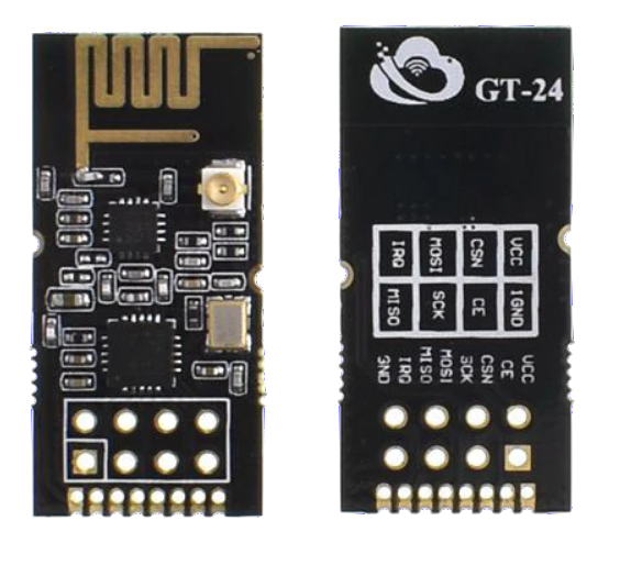
The GT-24 2.4G NRF24L01+PA+LNA is a high-performance wireless transceiver module operating in the 2.4GHz ISM band. It features power amplification (PA) and low noise amplification (LNA), which significantly enhance its transmission range and sensitivity. This module is widely used in Internet of Things (IoT) applications, remote control systems, wireless sensors, and other projects requiring reliable long-range communication.
Explore Projects Built with GT-24 2.4G NRF24L01+PA+LNA

Explore Projects Built with GT-24 2.4G NRF24L01+PA+LNA
Common Applications:
- IoT devices and smart home systems
- Wireless remote controls (e.g., drones, RC cars)
- Wireless sensor networks
- Industrial automation and telemetry
- Data transmission in robotics
Technical Specifications
The GT-24 module is based on the NRF24L01+ transceiver chip, enhanced with PA and LNA for extended range and improved signal quality. Below are the key technical details:
Key Specifications:
| Parameter | Value |
|---|---|
| Operating Frequency | 2.4GHz ISM band |
| Modulation | GFSK |
| Data Rate | 250kbps, 1Mbps, 2Mbps |
| Operating Voltage | 1.9V to 3.6V |
| Maximum Output Power | +20dBm |
| Sensitivity | -94dBm at 1Mbps, -89dBm at 2Mbps |
| Communication Range | Up to 1000 meters (line of sight) |
| Current Consumption | 115mA (TX at max power) |
| Interface | SPI |
| Antenna | External SMA antenna |
Pin Configuration:
The GT-24 module has an 8-pin interface. Below is the pinout description:
| Pin Number | Name | Description |
|---|---|---|
| 1 | GND | Ground connection |
| 2 | VCC | Power supply (1.9V to 3.6V, typically 3.3V) |
| 3 | CE | Chip Enable: Activates RX or TX mode |
| 4 | CSN | Chip Select Not: SPI chip select (active low) |
| 5 | SCK | Serial Clock: SPI clock input |
| 6 | MOSI | Master Out Slave In: SPI data input |
| 7 | MISO | Master In Slave Out: SPI data output |
| 8 | IRQ | Interrupt Request: Indicates data received or transmission complete |
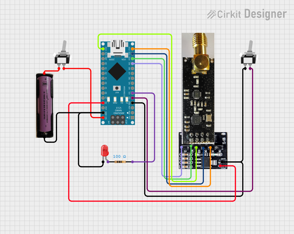
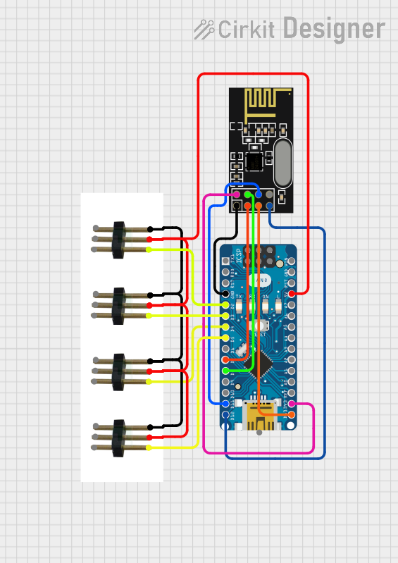
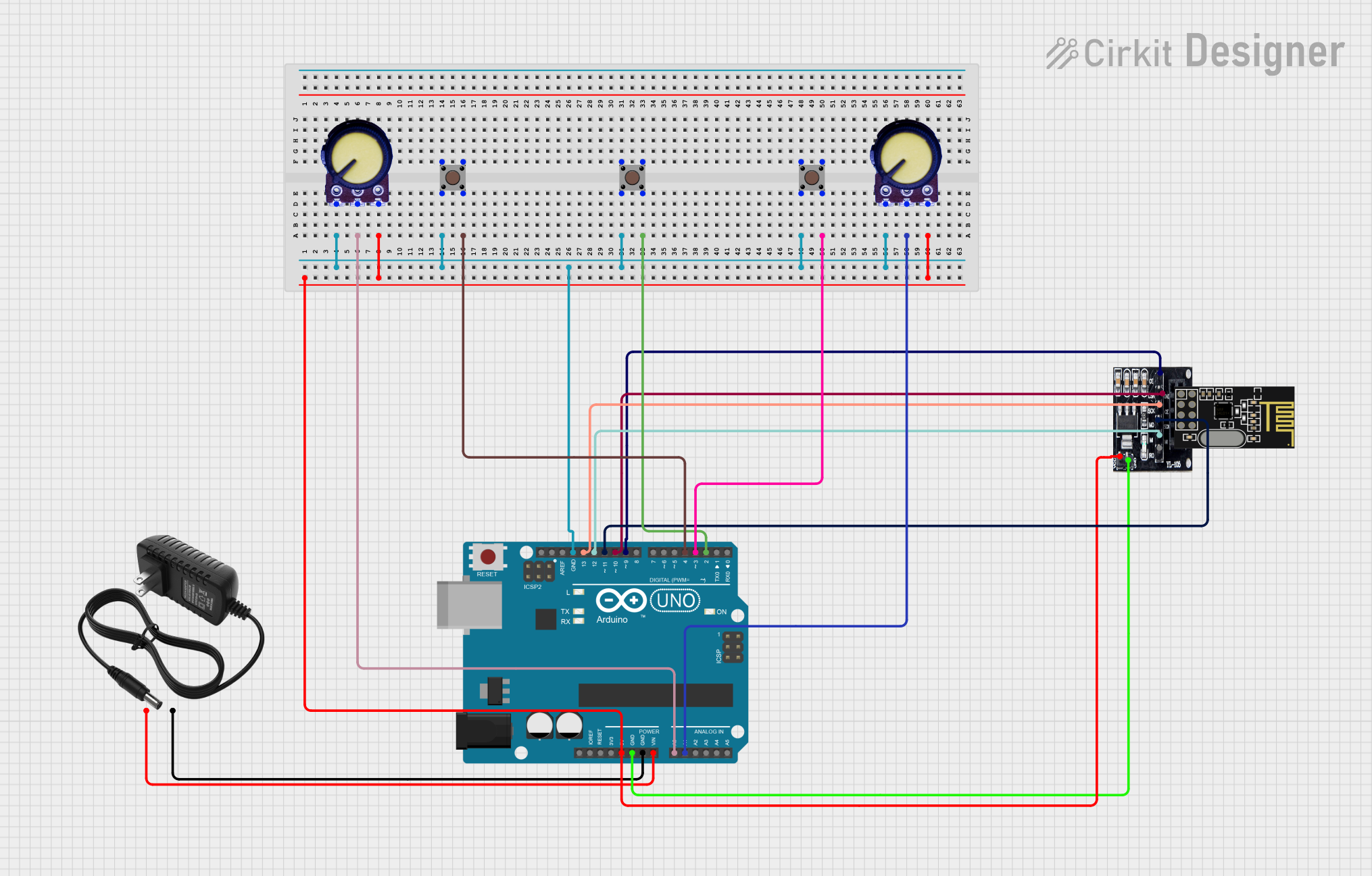
Usage Instructions
How to Use the GT-24 Module in a Circuit:
- Power Supply: Connect the VCC pin to a 3.3V power source. Do not exceed 3.6V to avoid damaging the module. Connect the GND pin to the ground of your circuit.
- SPI Interface: Connect the SPI pins (CSN, SCK, MOSI, MISO) to the corresponding SPI pins on your microcontroller.
- Control Pins:
- Connect the CE pin to a GPIO pin on your microcontroller to toggle between RX and TX modes.
- The IRQ pin can be connected to an interrupt-capable GPIO pin for event handling, but it is optional.
- Antenna: Attach the external SMA antenna to the module for optimal performance.
Important Considerations:
- Voltage Regulation: Ensure the module operates at 3.3V. If using a 5V microcontroller (e.g., Arduino UNO), use a level shifter or voltage divider for the SPI pins.
- Decoupling Capacitor: Place a 10µF capacitor close to the VCC and GND pins to stabilize the power supply.
- Antenna Placement: Position the antenna away from metal objects or other sources of interference for maximum range.
Example: Connecting to an Arduino UNO
Below is an example of how to connect the GT-24 module to an Arduino UNO and send data wirelessly.
Wiring:
| GT-24 Pin | Arduino UNO Pin |
|---|---|
| GND | GND |
| VCC | 3.3V |
| CE | Pin 9 |
| CSN | Pin 10 |
| SCK | Pin 13 |
| MOSI | Pin 11 |
| MISO | Pin 12 |
| IRQ | Not connected |
Arduino Code:
#include <SPI.h>
#include <nRF24L01.h>
#include <RF24.h>

// Define CE and CSN pins
#define CE_PIN 9
#define CSN_PIN 10

// Create an RF24 object
RF24 radio(CE_PIN, CSN_PIN);

// Define the address for communication
const byte address[6] = "00001";

void setup() {
  // Initialize serial communication
  Serial.begin(9600);

  // Initialize the RF24 module
  radio.begin();

  // Set the address for the transmitter
  radio.openWritingPipe(address);

  // Set RF24 module to send data
  radio.setPALevel(RF24_PA_HIGH);

  // Start the module in TX mode
  radio.stopListening();
}

void loop() {
  // Data to send
  const char text[] = "Hello, World!";

  // Send the data
  bool success = radio.write(&text, sizeof(text));

  // Print the result
  if (success) {
    Serial.println("Data sent successfully!");
  } else {
    Serial.println("Data transmission failed.");
  }

  // Wait before sending the next message
  delay(1000);
}
Troubleshooting and FAQs
Common Issues:
No Communication Between Modules:
- Ensure both modules are using the same address and data rate.
- Verify the wiring and SPI connections.
- Check the power supply voltage (3.3V) and ensure it is stable.
Short Range or Poor Signal:
- Ensure the antenna is securely connected and positioned correctly.
- Avoid interference from other 2.4GHz devices (e.g., Wi-Fi routers).
- Use a decoupling capacitor near the module's power pins.
Module Not Responding:
- Verify the CE and CSN pin connections.
- Ensure the SPI clock speed is within the module's specifications.
FAQs:
Q: Can I use the GT-24 module with a 5V microcontroller?
A: Yes, but you must use a level shifter or voltage divider for the SPI pins to avoid damaging the module.
Q: What is the maximum range of the GT-24 module?
A: The module can achieve up to 1000 meters in line-of-sight conditions with a proper antenna.
Q: How do I improve the reliability of communication?
A: Use a lower data rate (e.g., 250kbps) for better range and reliability, and ensure a stable power supply with proper decoupling.
Q: Can I connect multiple GT-24 modules in a network?
A: Yes, the NRF24L01+ supports multi-node communication using unique addresses for each module.