How to Use LM75A: Examples, Pinouts, and Specs
Introduction
The LM75A is a digital temperature sensor with an I2C interface, designed for precise temperature measurement and monitoring. It operates over a wide temperature range of -55°C to +125°C with a resolution of 0.5°C. The LM75A includes programmable over-temperature and under-temperature alarms, making it ideal for applications requiring temperature control and safety monitoring.
Explore Projects Built with LM75A


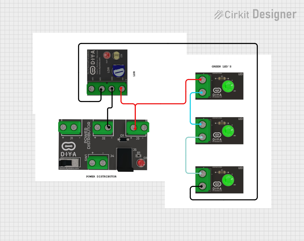
Explore Projects Built with LM75A
Common Applications
- HVAC systems for temperature regulation
- Over-temperature protection in electronic devices
- Industrial temperature monitoring
- Battery management systems
- Home automation and IoT devices
Technical Specifications
Key Technical Details
- Temperature Range: -55°C to +125°C
- Resolution: 0.5°C
- Supply Voltage: 2.7V to 5.5V
- Communication Protocol: I2C (up to 400 kHz)
- Accuracy: ±2°C (typical) from -25°C to +100°C
- Alert Function: Programmable over-temperature and under-temperature alerts
- Power Consumption: 300 µA (typical operating current)
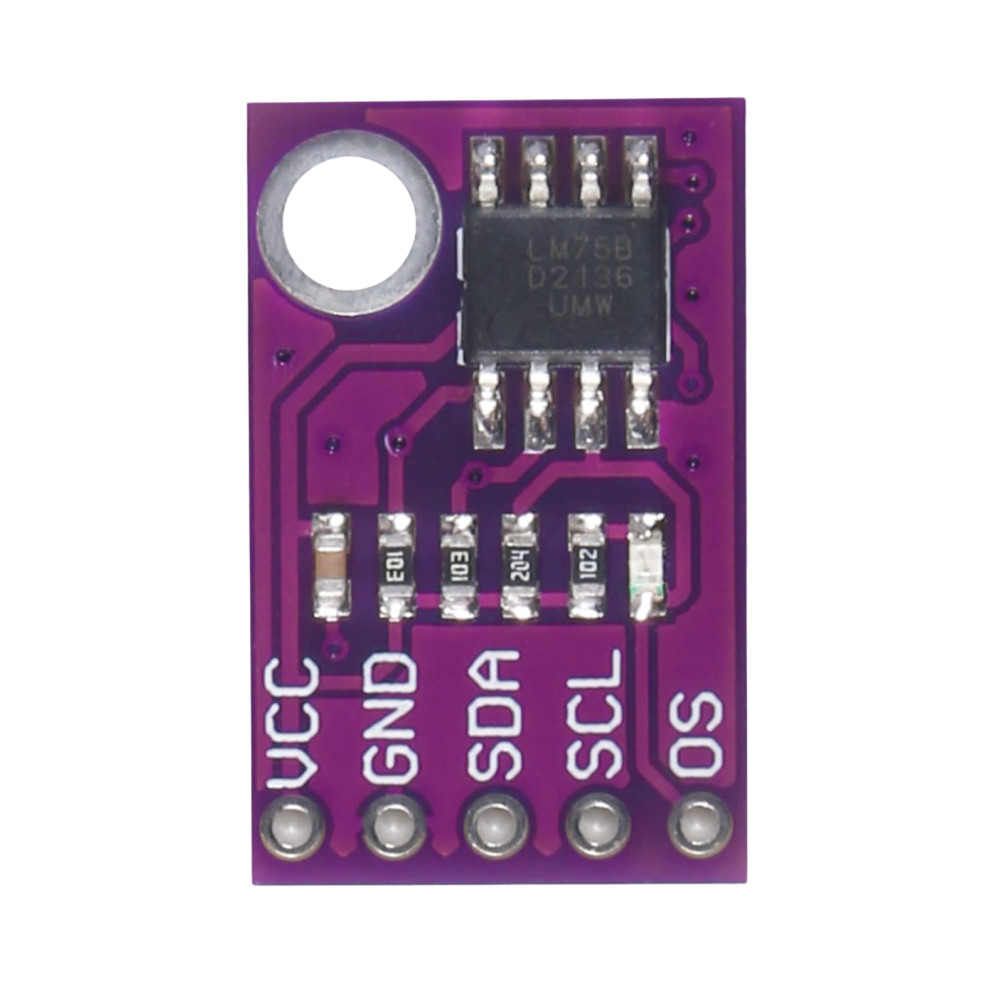
Pin Configuration and Descriptions
The LM75A is typically available in an 8-pin package. Below is the pinout and description:
| Pin Number | Pin Name | Description |
|---|---|---|
| 1 | SDA | Serial Data Line for I2C communication. |
| 2 | SCL | Serial Clock Line for I2C communication. |
| 3 | OS | Over-temperature Shutdown (alert output, open-drain). |
| 4 | GND | Ground. |
| 5 | A2 | Address Pin 2 (used to set the I2C address). |
| 6 | A1 | Address Pin 1 (used to set the I2C address). |
| 7 | A0 | Address Pin 0 (used to set the I2C address). |
| 8 | VCC | Power Supply (2.7V to 5.5V). |
I2C Address
The LM75A's I2C address is determined by the states of the A2, A1, and A0 pins. The base address is 0x48, and the full address is calculated as:
Address = 0x48 + (A2 * 4) + (A1 * 2) + A0
For example:
- If A2 = 0, A1 = 0, A0 = 1, the address is
0x49.
Usage Instructions
How to Use the LM75A in a Circuit
- Power Supply: Connect the VCC pin to a 3.3V or 5V power source and the GND pin to ground.
- I2C Communication: Connect the SDA and SCL pins to the corresponding I2C lines of your microcontroller. Use pull-up resistors (typically 4.7 kΩ) on both lines.
- Address Configuration: Set the A2, A1, and A0 pins to configure the I2C address. These can be connected to VCC (logic high) or GND (logic low).
- Alert Pin (Optional): Connect the OS pin to a microcontroller GPIO pin or an external circuit to monitor over-temperature alerts.
Best Practices
- Use decoupling capacitors (e.g., 0.1 µF) between VCC and GND to reduce noise.
- Ensure proper pull-up resistors are used on the I2C lines for reliable communication.
- Avoid placing the LM75A near heat sources to ensure accurate temperature readings.
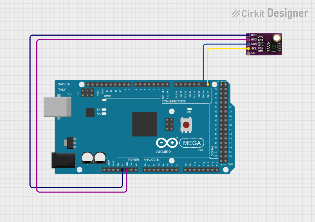
Example: Connecting LM75A to Arduino UNO
Below is an example of how to interface the LM75A with an Arduino UNO and read temperature data:
Circuit Diagram
- Connect
VCCto the Arduino's5Vpin. - Connect
GNDto the Arduino'sGNDpin. - Connect
SDAto the Arduino'sA4pin. - Connect
SCLto the Arduino'sA5pin. - Use 4.7 kΩ pull-up resistors on the SDA and SCL lines.
Arduino Code
#include <Wire.h>

#define LM75A_ADDRESS 0x48 // Default I2C address of LM75A

void setup() {
  Wire.begin(); // Initialize I2C communication
  Serial.begin(9600); // Start serial communication for debugging
}

void loop() {
  float temperature = readTemperature();
  Serial.print("Temperature: ");
  Serial.print(temperature);
  Serial.println(" °C");
  delay(1000); // Wait 1 second before the next reading
}

float readTemperature() {
  Wire.beginTransmission(LM75A_ADDRESS); // Start communication with LM75A
  Wire.write(0x00); // Point to the temperature register
  Wire.endTransmission();

  Wire.requestFrom(LM75A_ADDRESS, 2); // Request 2 bytes from LM75A
  if (Wire.available() == 2) {
    // Read the two bytes of temperature data
    uint8_t msb = Wire.read(); // Most significant byte
    uint8_t lsb = Wire.read(); // Least significant byte

    // Combine the bytes and convert to temperature
    int16_t rawTemp = (msb << 8) | lsb;
    rawTemp >>= 7; // Right shift to remove unused bits
    return rawTemp * 0.5; // Each bit represents 0.5°C
  }
  return NAN; // Return NaN if no data is available
}
Troubleshooting and FAQs
Common Issues
No Temperature Data Received
- Cause: Incorrect I2C address or wiring.
- Solution: Verify the I2C address based on the A2, A1, and A0 pin configuration. Check the SDA and SCL connections and ensure pull-up resistors are in place.
Inaccurate Temperature Readings
- Cause: Heat sources near the sensor or poor decoupling.
- Solution: Place the LM75A away from heat-generating components. Add a 0.1 µF capacitor between VCC and GND.
Alert Pin Not Functioning
- Cause: Incorrect configuration of the OS pin or alert thresholds.
- Solution: Verify the alert thresholds are correctly programmed via the LM75A's configuration register.
FAQs
Q: Can the LM75A operate at 3.3V?
A: Yes, the LM75A supports a supply voltage range of 2.7V to 5.5V.Q: What is the default I2C address of the LM75A?
A: The default address is0x48when A2, A1, and A0 are all connected to GND.Q: How do I change the temperature alert thresholds?
A: The alert thresholds can be configured by writing to the LM75A's over-temperature and hysteresis registers via I2C.Q: Can the LM75A measure negative temperatures?
A: Yes, the LM75A can measure temperatures as low as -55°C. Negative temperatures are represented in two's complement format.