How to Use B-L475E-IOT01A: Examples, Pinouts, and Specs
Introduction
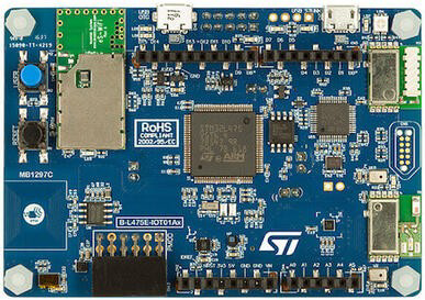
The B-L475E-IOT01A is a development board manufactured by STM32, designed to simplify the development of Internet of Things (IoT) applications. It is powered by the STM32L475 microcontroller, which is optimized for low-power operation. The board integrates a wide range of sensors, connectivity options (Wi-Fi, Bluetooth, NFC), and expansion interfaces, making it a versatile platform for prototyping and deploying IoT solutions.
Explore Projects Built with B-L475E-IOT01A


Explore Projects Built with B-L475E-IOT01A
Common Applications and Use Cases
- Environmental monitoring (temperature, humidity, air quality)
- Smart home devices
- Wearable technology
- Industrial IoT (IIoT) applications
- Prototyping for connected devices
- Battery-operated IoT systems
Technical Specifications
Key Technical Details
| Feature | Specification |
|---|---|
| Microcontroller | STM32L475VG (ARM Cortex-M4, 80 MHz, 1 MB Flash, 128 KB RAM) |
| Connectivity | Wi-Fi (ISM43362), Bluetooth Low Energy (BLE), NFC (ST25DV04K) |
| Sensors | Temperature, humidity, pressure, magnetometer, gyroscope, accelerometer, |
| microphone, and Time-of-Flight (ToF) distance sensor | |
| Power Supply | USB (5V) or external battery (3.3V to 5V) |
| Operating Voltage | 3.3V |
| Expansion Interfaces | Arduino Uno V3-compatible headers, STMod+ connector |
| Debugging | Integrated ST-LINK/V2-1 debugger/programmer |
| Dimensions | 95 mm x 50 mm |
Pin Configuration and Descriptions
The B-L475E-IOT01A features Arduino Uno V3-compatible headers for easy prototyping. Below is the pinout for the Arduino header:
Arduino Header Pinout
| Pin Name | Function | Description |
|---|---|---|
| A0-A5 | Analog Input | 6 analog input pins for sensors or other devices |
| D0-D13 | Digital I/O | 14 digital I/O pins (PWM available on some pins) |
| 3.3V | Power Output | 3.3V power supply for external components |
| 5V | Power Output | 5V power supply for external components |
| GND | Ground | Common ground |
| VIN | Power Input | External power input (3.3V to 5V) |
| SDA/SCL | I2C Communication | I2C data and clock lines |
| TX/RX | UART Communication | Serial communication pins |
STMod+ Connector Pinout
| Pin Name | Function | Description |
|---|---|---|
| 1-2 | Power Supply | 3.3V and GND |
| 3-4 | UART | TX and RX for serial communication |
| 5-6 | I2C | SDA and SCL for I2C communication |
| 7-8 | GPIO | General-purpose input/output pins |
Usage Instructions
How to Use the Component in a Circuit
Powering the Board:
- Connect the board to a computer or USB power source using a micro-USB cable.
- Alternatively, supply power through the VIN pin (3.3V to 5V) for battery-operated applications.
Connecting Sensors and Peripherals:
- Use the Arduino-compatible headers to connect external sensors or actuators.
- For I2C devices, connect to the SDA and SCL pins. For UART devices, use the TX and RX pins.
Programming the Board:
- Install the STM32CubeIDE or Arduino IDE (with STM32 support) on your computer.
- Connect the board via USB and select the appropriate COM port in the IDE.
- Write and upload your code to the board.
Using Built-in Sensors:
- The board includes several onboard sensors (e.g., temperature, humidity, accelerometer). These can be accessed using STM32 HAL libraries or Arduino libraries.
Important Considerations and Best Practices
- Power Consumption: Use the low-power features of the STM32L475 microcontroller to extend battery life in portable applications.
- Debugging: Use the integrated ST-LINK/V2-1 debugger for efficient debugging and programming.
- Firmware Updates: Keep the firmware updated to ensure compatibility with the latest libraries and tools.
- Connectivity: Ensure proper configuration of Wi-Fi and Bluetooth settings for reliable communication.
Example Code for Arduino IDE
The following example demonstrates how to read temperature data from the onboard HTS221 sensor and print it to the serial monitor.
#include <Wire.h>
#include <HTS221Sensor.h> // Include the library for the HTS221 sensor

// Define I2C address for the HTS221 sensor
#define HTS221_I2C_ADDRESS 0x5F

// Create an instance of the HTS221 sensor
HTS221Sensor hts221(&Wire);

void setup() {
  Serial.begin(9600); // Initialize serial communication
  Wire.begin();       // Initialize I2C communication

  // Initialize the HTS221 sensor
  if (hts221.begin(HTS221_I2C_ADDRESS)) {
    Serial.println("HTS221 sensor initialized successfully.");
  } else {
    Serial.println("Failed to initialize HTS221 sensor.");
    while (1); // Halt execution if initialization fails
  }
}

void loop() {
  float temperature;

  // Read temperature from the HTS221 sensor
  if (hts221.getTemperature(&temperature)) {
    Serial.print("Temperature: ");
    Serial.print(temperature);
    Serial.println(" °C");
  } else {
    Serial.println("Failed to read temperature.");
  }

  delay(1000); // Wait for 1 second before the next reading
}
Troubleshooting and FAQs
Common Issues and Solutions
Board Not Detected by IDE:
- Ensure the USB cable is properly connected and functional.
- Verify that the correct COM port is selected in the IDE.
- Update the ST-LINK driver if necessary.
Sensors Not Responding:
- Check the I2C or SPI connections for external sensors.
- Ensure the correct sensor address is used in the code.
Wi-Fi or Bluetooth Not Connecting:
- Verify the network credentials (SSID and password) in the code.
- Ensure the board is within range of the Wi-Fi router or Bluetooth device.
High Power Consumption:
- Use the low-power modes of the STM32L475 microcontroller.
- Disable unused peripherals to reduce power consumption.
FAQs
Q: Can I use the B-L475E-IOT01A with the Arduino IDE?
A: Yes, the board is compatible with the Arduino IDE. Install the STM32 core for Arduino to get started.
Q: How do I update the firmware on the board?
A: Use the STM32CubeProgrammer tool to update the firmware via the USB interface.
Q: What is the range of the onboard Wi-Fi module?
A: The range depends on environmental factors but typically covers 30-50 meters indoors.
Q: Can I power the board with a battery?
A: Yes, the board can be powered using an external battery connected to the VIN pin (3.3V to 5V).