How to Use DC Isolator: Examples, Pinouts, and Specs
Introduction
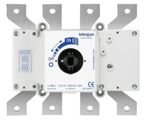
A DC isolator is a crucial safety device used to disconnect a direct current (DC) circuit from its power source. It ensures that no current flows through the circuit, allowing for safe maintenance, servicing, or troubleshooting of electrical equipment. DC isolators are commonly used in solar power systems, battery storage systems, and industrial DC applications to protect both personnel and equipment.
Explore Projects Built with DC Isolator


Explore Projects Built with DC Isolator
Common Applications and Use Cases
- Solar photovoltaic (PV) systems to isolate solar panels from inverters.
- Battery storage systems for safe maintenance and fault isolation.
- Industrial DC circuits to ensure safety during equipment servicing.
- Electric vehicle (EV) charging stations for emergency disconnection.
- DC motor control systems to isolate power during repairs.
Technical Specifications
Below are the key technical details of a typical DC isolator:
| Parameter | Specification |
|---|---|
| Rated Voltage | 12V to 1000V DC (varies by model) |
| Rated Current | 10A to 250A (varies by model) |
| Poles | 2-pole or 4-pole |
| Operating Temperature | -25°C to +70°C |
| Insulation Resistance | ≥ 10 MΩ |
| Enclosure Protection | IP65 (weatherproof models available) |
| Mounting Type | DIN rail or surface mount |
| Mechanical Durability | ≥ 10,000 operations |
| Electrical Durability | ≥ 1,000 operations |
Pin Configuration and Descriptions
DC isolators typically do not have "pins" like integrated circuits but instead feature input and output terminals. Below is a description of the terminal configuration:
| Terminal | Description |
|---|---|
| Input (+) | Positive terminal for the DC power source input. |
| Input (-) | Negative terminal for the DC power source input. |
| Output (+) | Positive terminal for the DC load connection. |
| Output (-) | Negative terminal for the DC load connection. |
| Ground (if available) | Optional grounding terminal for safety. |
Usage Instructions
How to Use the DC Isolator in a Circuit
- Identify the Input and Output Terminals: Ensure you correctly identify the input terminals (connected to the DC power source) and the output terminals (connected to the load).
- Mount the Isolator: Securely mount the DC isolator on a DIN rail or surface, depending on the model.
- Connect the Wires:
- Connect the positive and negative wires from the DC power source to the input terminals.
- Connect the positive and negative wires from the load to the output terminals.
- If the isolator has a ground terminal, connect it to the system ground for added safety.
- Switch Operation:
- Turn the isolator to the "ON" position to allow current flow.
- Turn the isolator to the "OFF" position to disconnect the circuit.
Important Considerations and Best Practices
- Voltage and Current Ratings: Always ensure the isolator's voltage and current ratings match or exceed the requirements of your circuit.
- Polarity: Maintain correct polarity when connecting the input and output terminals.
- Weatherproofing: For outdoor applications, use an IP65-rated isolator to protect against dust and moisture.
- Regular Maintenance: Periodically inspect the isolator for signs of wear, corrosion, or damage.
- Emergency Use: Ensure the isolator is easily accessible in case of an emergency.
Example: Using a DC Isolator in a Solar PV System
In a solar photovoltaic system, the DC isolator is installed between the solar panels and the inverter. This allows the panels to be safely disconnected during maintenance or in case of a fault.
Arduino Integration
While DC isolators are not directly controlled by microcontrollers like Arduino, they can be used in conjunction with relays or sensors to monitor the circuit's status. Below is an example of how to monitor the state of a DC isolator using an Arduino and a digital input pin:
// Example code to monitor the state of a DC isolator using Arduino
const int isolatorPin = 2; // Digital pin connected to the isolator's status output
const int ledPin = 13;     // Built-in LED to indicate isolator status

void setup() {
  pinMode(isolatorPin, INPUT); // Set the isolator pin as input
  pinMode(ledPin, OUTPUT);     // Set the LED pin as output
  Serial.begin(9600);          // Initialize serial communication
}

void loop() {
  int isolatorState = digitalRead(isolatorPin); // Read the isolator's state

  if (isolatorState == HIGH) {
    // If isolator is ON, turn off the LED and print status
    digitalWrite(ledPin, LOW);
    Serial.println("DC Isolator is ON: Circuit is connected.");
  } else {
    // If isolator is OFF, turn on the LED and print status
    digitalWrite(ledPin, HIGH);
    Serial.println("DC Isolator is OFF: Circuit is disconnected.");
  }

  delay(1000); // Wait for 1 second before checking again
}
Troubleshooting and FAQs
Common Issues and Solutions
| Issue | Solution |
|---|---|
| Isolator does not disconnect the circuit. | Check for proper wiring and ensure the isolator is rated for the circuit's voltage and current. |
| Overheating of the isolator. | Verify that the isolator is not overloaded and is operating within its rated capacity. |
| Difficulty operating the switch. | Inspect for mechanical damage or debris obstructing the switch mechanism. |
| Corrosion or damage to terminals. | Clean the terminals and ensure proper weatherproofing for outdoor installations. |
FAQs
Can a DC isolator be used for AC circuits? No, DC isolators are specifically designed for direct current and may not function correctly or safely in AC circuits.
What is the difference between a DC isolator and a circuit breaker? A DC isolator is a manual switch used for isolation, while a circuit breaker is an automatic device that trips during overcurrent or short circuits.
How often should a DC isolator be inspected? It is recommended to inspect the isolator at least once a year or as part of routine system maintenance.
Can I install a DC isolator myself? While installation is straightforward, it is recommended to consult a qualified electrician to ensure safety and compliance with local regulations.