How to Use ES8388 Audio Codec Module: Examples, Pinouts, and Specs
Introduction
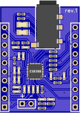
The ES8388 Audio Codec Module (Manufacturer: PCB Artists, Part ID: PCBA2103) is a low-power, high-performance audio codec designed for stereo audio playback and recording. It integrates a high-quality digital-to-analog converter (DAC) and analog-to-digital converter (ADC), making it ideal for applications requiring audio signal processing. The module is widely used in portable devices, IoT audio systems, and embedded audio solutions due to its compact design and versatile functionality.
Explore Projects Built with ES8388 Audio Codec Module
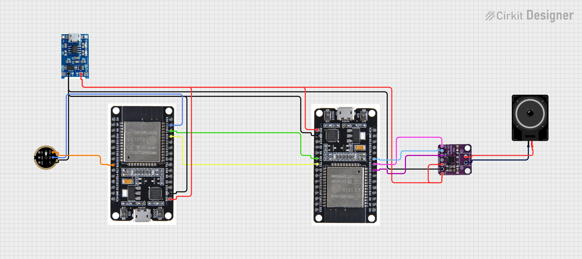
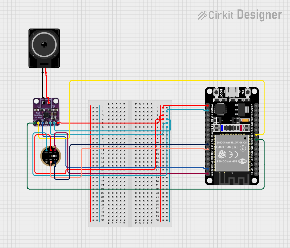
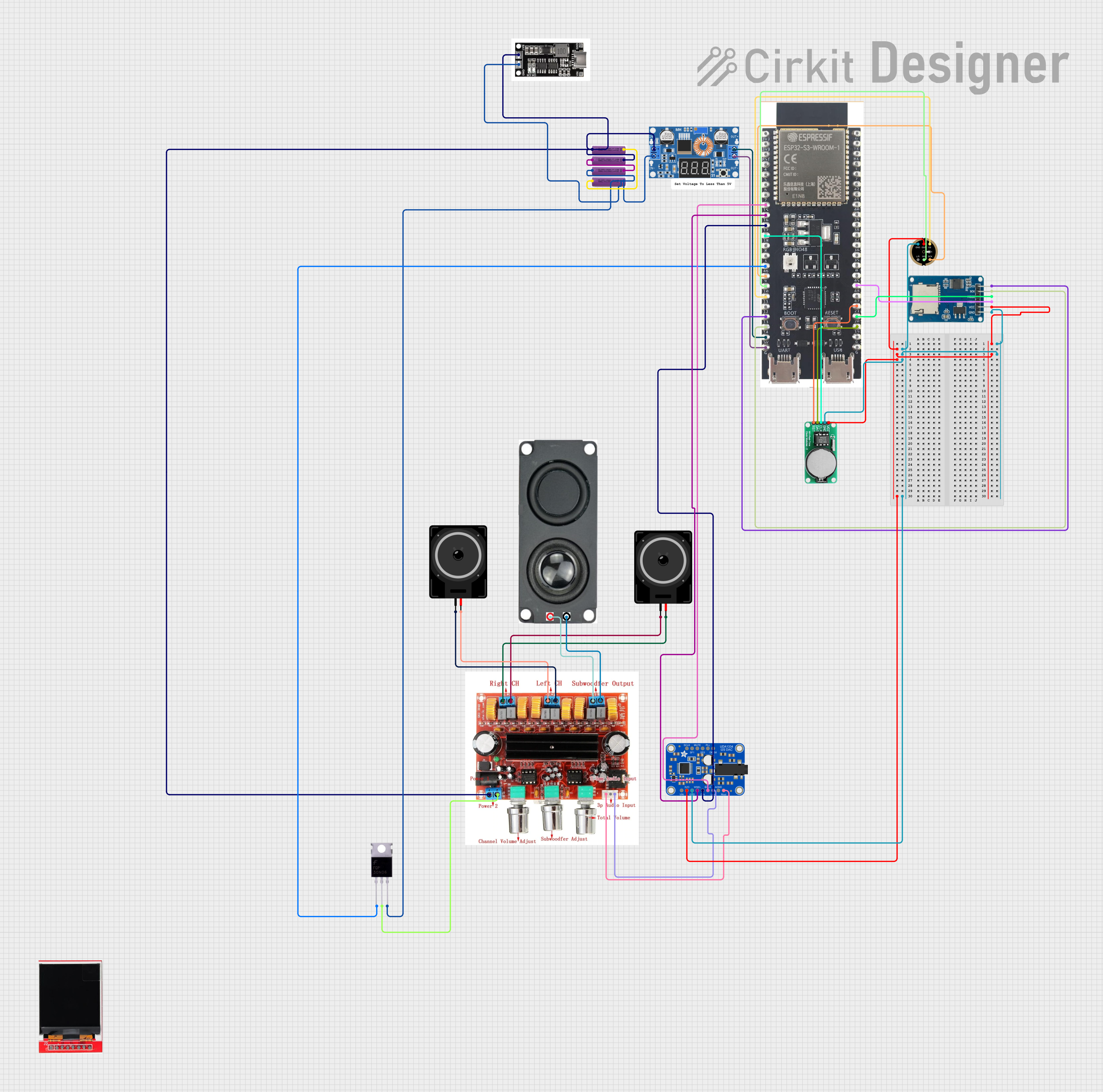
Explore Projects Built with ES8388 Audio Codec Module
Common Applications
- Portable audio devices (e.g., MP3 players, voice recorders)
- IoT devices with audio capabilities
- Embedded systems requiring audio input/output
- Smart home devices (e.g., smart speakers, intercoms)
- Audio processing and effects systems
Technical Specifications
Key Technical Details
| Parameter | Specification |
|---|---|
| Supply Voltage (Analog) | 3.3V |
| Supply Voltage (Digital) | 1.8V to 3.3V |
| Power Consumption | Low-power operation |
| Audio Channels | Stereo (2 channels) |
| Sampling Rate | Up to 96 kHz |
| Signal-to-Noise Ratio (SNR) | 100 dB (Playback), 92 dB (Recording) |
| Total Harmonic Distortion | -85 dB |
| Communication Interface | I²C (control) and I²S/PCM (audio data) |
| Package Type | QFN-28 |
Pin Configuration and Descriptions
The ES8388 module has 28 pins. Below is a summary of the key pins:
| Pin Number | Pin Name | Description |
|---|---|---|
| 1 | MCLK | Master clock input for audio processing |
| 2 | SCLK | Serial clock for I²S/PCM interface |
| 3 | LRCK | Left/Right clock for I²S/PCM interface |
| 4 | SDIN | Serial data input for audio playback |
| 5 | SDOUT | Serial data output for audio recording |
| 6 | SDA | I²C data line for control interface |
| 7 | SCL | I²C clock line for control interface |
| 8 | VCCA | Analog power supply (3.3V) |
| 9 | VCCD | Digital power supply (1.8V to 3.3V) |
| 10 | AGND | Analog ground |
| 11 | DGND | Digital ground |
| 12 | MIC1P | Microphone input 1 positive terminal |
| 13 | MIC1N | Microphone input 1 negative terminal |
| 14 | MIC2P | Microphone input 2 positive terminal |
| 15 | MIC2N | Microphone input 2 negative terminal |
| 16 | HPLOUT | Headphone left channel output |
| 17 | HPROUT | Headphone right channel output |
| 18 | LINEINL | Line-in left channel input |
| 19 | LINEINR | Line-in right channel input |
| 20 | NC | Not connected |
Usage Instructions
How to Use the ES8388 in a Circuit
- Power Supply: Connect the analog power supply (VCCA) to 3.3V and the digital power supply (VCCD) to a voltage between 1.8V and 3.3V. Ensure proper grounding by connecting AGND and DGND to the circuit ground.
- Clock Signals: Provide a stable master clock (MCLK) and configure the serial clock (SCLK) and left/right clock (LRCK) for the I²S/PCM interface.
- Audio Input/Output:
- For audio playback, connect the audio source to the SDIN pin and configure the I²S interface.
- For audio recording, connect microphones to MIC1P/MIC1N or MIC2P/MIC2N and read data from the SDOUT pin.
- Control Interface: Use the I²C interface (SDA and SCL pins) to configure the codec settings, such as volume, sampling rate, and input/output selection.
- Output Connections: Connect headphones or speakers to HPLOUT and HPROUT for audio playback.
Important Considerations and Best Practices
- Use decoupling capacitors near the power supply pins to reduce noise.
- Ensure proper impedance matching for microphone and headphone connections.
- Configure the I²C address of the ES8388 correctly if multiple devices are on the same bus.
- Avoid exceeding the maximum voltage ratings to prevent damage to the module.
- Use a stable clock source for MCLK to ensure accurate audio processing.
Example: Connecting the ES8388 to an Arduino UNO
The ES8388 can be controlled using the Arduino UNO via the I²C interface. Below is an example code snippet to initialize the ES8388:
#include <Wire.h> // Include the Wire library for I²C communication

#define ES8388_I2C_ADDRESS 0x10 // Default I²C address of the ES8388

void setup() {
  Wire.begin(); // Initialize I²C communication
  Serial.begin(9600); // Initialize serial communication for debugging

  // Initialize the ES8388 codec
  configureES8388();
}

void loop() {
  // Main loop can be used for audio processing or other tasks
}

void configureES8388() {
  // Example: Set ES8388 to playback mode
  Wire.beginTransmission(ES8388_I2C_ADDRESS);
  Wire.write(0x02); // Register address for system control
  Wire.write(0x01); // Example value to enable playback
  Wire.endTransmission();

  Serial.println("ES8388 configured for playback mode.");
}
Troubleshooting and FAQs
Common Issues and Solutions
No Audio Output:
- Ensure the power supply connections (VCCA and VCCD) are correct and stable.
- Verify that the MCLK, SCLK, and LRCK signals are properly configured.
- Check the I²C configuration to ensure the codec is set to playback mode.
Distorted Audio:
- Verify that the input signal levels are within the supported range.
- Check for proper grounding and minimize noise in the circuit.
- Ensure the sampling rate and bit depth are correctly configured.
I²C Communication Failure:
- Confirm the I²C address of the ES8388 (default: 0x10).
- Check the pull-up resistors on the SDA and SCL lines.
- Ensure the Arduino UNO and ES8388 share a common ground.
FAQs
Q1: Can the ES8388 be used with a 5V microcontroller?
A1: Yes, but level shifters are required for the I²C and I²S signals, as the ES8388 operates at 3.3V logic levels.
Q2: What is the maximum sampling rate supported by the ES8388?
A2: The ES8388 supports sampling rates up to 96 kHz.
Q3: How do I configure the ES8388 for mono audio?
A3: Use the I²C interface to configure the codec for mono operation by selecting a single channel for input/output.
Q4: Can I use the ES8388 without an external MCLK source?
A4: No, the ES8388 requires a stable MCLK signal for proper operation.
This concludes the documentation for the ES8388 Audio Codec Module. For further assistance, refer to the manufacturer's datasheet or contact PCB Artists.