Cirkit Designer Logo
Cirkit Designer
Your all-in-one circuit design IDE
Home / 
Component Documentation

How to Use BDS V.2: Examples, Pinouts, and Specs

Image of BDS V.2
Cirkit Designer LogoDesign with BDS V.2 in Cirkit Designer

Introduction

The BDS V.2 is an advanced electronic component designed by Cloudberry Inc. It is a versatile circuit board or device that integrates into various electronic systems. The BDS V.2 is known for its reliability and adaptability, making it suitable for a wide range of applications, including but not limited to automation systems, consumer electronics, and hobbyist projects such as those involving Arduino platforms.

Explore Projects Built with BDS V.2

Use Cirkit Designer to design, explore, and prototype these projects online. Some projects support real-time simulation. Click "Open Project" to start designing instantly!
Battery-Powered Adjustable Voltage Regulator with Li-ion 18650 Batteries and BMS
Image of mini ups: A project utilizing BDS V.2 in a practical application
This circuit is a power management system that uses four Li-ion 18650 batteries connected to a 2S 30A BMS for battery management and protection. The system includes step-up and step-down voltage regulators to provide adjustable output voltages, controlled by a rocker switch, and multiple DC jacks for power input and output.
Cirkit Designer LogoOpen Project in Cirkit Designer
Li-ion Battery Management and Monitoring System with Voltage Regulation and Relay Control
Image of Portable Inverter: A project utilizing BDS V.2 in a practical application
This is a power management system with a series-connected battery pack managed by a BMS, providing regulated power to a microcontroller and a fan. It includes voltage and current sensing, a relay for load control, and a step-up converter for an external power source.
Cirkit Designer LogoOpen Project in Cirkit Designer
Solar-Powered GSM/GPRS+GPS Tracker with Seeeduino XIAO
Image of SOS System : A project utilizing BDS V.2 in a practical application
This circuit features an Ai Thinker A9G development board for GSM/GPRS and GPS/BDS connectivity, interfaced with a Seeeduino XIAO microcontroller for control and data processing. A solar cell, coupled with a TP4056 charging module, charges a 3.3V battery, which powers the system through a 3.3V regulator ensuring stable operation. The circuit likely serves for remote data communication and location tracking, with the capability to be powered by renewable energy and interfaced with additional sensors or input devices via the Seeeduino XIAO.
Cirkit Designer LogoOpen Project in Cirkit Designer
Battery-Powered Boost Converter with USB Type-C and BMS
Image of Weird Case: A project utilizing BDS V.2 in a practical application
This circuit is a power management and conversion system that includes a boost converter, battery management system (BMS), and various MOSFETs and passive components. It is designed to regulate and boost the voltage from a 2000mAh battery, providing stable power output through a USB Type C interface. The circuit also includes protection and switching mechanisms to ensure safe and efficient power delivery.
Cirkit Designer LogoOpen Project in Cirkit Designer

Explore Projects Built with BDS V.2

Use Cirkit Designer to design, explore, and prototype these projects online. Some projects support real-time simulation. Click "Open Project" to start designing instantly!
Image of mini ups: A project utilizing BDS V.2 in a practical application
Battery-Powered Adjustable Voltage Regulator with Li-ion 18650 Batteries and BMS
This circuit is a power management system that uses four Li-ion 18650 batteries connected to a 2S 30A BMS for battery management and protection. The system includes step-up and step-down voltage regulators to provide adjustable output voltages, controlled by a rocker switch, and multiple DC jacks for power input and output.
Cirkit Designer LogoOpen Project in Cirkit Designer
Image of Portable Inverter: A project utilizing BDS V.2 in a practical application
Li-ion Battery Management and Monitoring System with Voltage Regulation and Relay Control
This is a power management system with a series-connected battery pack managed by a BMS, providing regulated power to a microcontroller and a fan. It includes voltage and current sensing, a relay for load control, and a step-up converter for an external power source.
Cirkit Designer LogoOpen Project in Cirkit Designer
Image of SOS System : A project utilizing BDS V.2 in a practical application
Solar-Powered GSM/GPRS+GPS Tracker with Seeeduino XIAO
This circuit features an Ai Thinker A9G development board for GSM/GPRS and GPS/BDS connectivity, interfaced with a Seeeduino XIAO microcontroller for control and data processing. A solar cell, coupled with a TP4056 charging module, charges a 3.3V battery, which powers the system through a 3.3V regulator ensuring stable operation. The circuit likely serves for remote data communication and location tracking, with the capability to be powered by renewable energy and interfaced with additional sensors or input devices via the Seeeduino XIAO.
Cirkit Designer LogoOpen Project in Cirkit Designer
Image of Weird Case: A project utilizing BDS V.2 in a practical application
Battery-Powered Boost Converter with USB Type-C and BMS
This circuit is a power management and conversion system that includes a boost converter, battery management system (BMS), and various MOSFETs and passive components. It is designed to regulate and boost the voltage from a 2000mAh battery, providing stable power output through a USB Type C interface. The circuit also includes protection and switching mechanisms to ensure safe and efficient power delivery.
Cirkit Designer LogoOpen Project in Cirkit Designer

Common Applications and Use Cases

  • Automation control systems
  • Robotics
  • DIY electronics projects
  • Sensor interfacing
  • Signal processing

Technical Specifications

The BDS V.2 is built to meet rigorous technical standards. Below are the key specifications and pin configurations for the component.

Key Technical Details

Specification Value Description
Operating Voltage TBD V The voltage range the BDS V.2 operates within.
Current Rating TBD mA Maximum current the component can handle.
Power Rating TBD W Total power consumption of the device.
Communication TBD (e.g., I2C, SPI, UART) The communication protocols supported by BDS V.2.
Operating Temperature TBD °C The range of temperatures over which the device can operate safely.

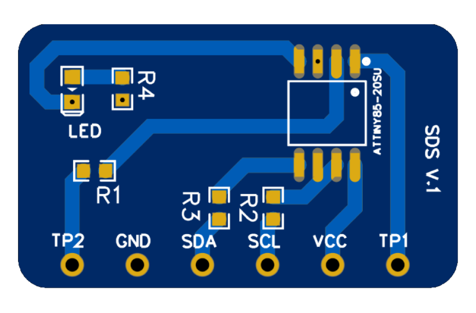
Pin Configuration and Descriptions

Pin Number Name Description
1 VCC Power supply input. Connect to TBD V.
2 GND Ground connection.
3 TX Transmit pin for serial communication.
4 RX Receive pin for serial communication.
5 SCL Serial Clock for I2C communication.
6 SDA Serial Data for I2C communication.
... ... Additional pins as per the BDS V.2 specifications.

Note: Replace TBD with actual values once they are provided by the manufacturer.

Usage Instructions

Integrating BDS V.2 into a Circuit

  1. Power Supply: Ensure that the power supply matches the operating voltage of the BDS V.2. Incorrect voltage can damage the component.
  2. Communication: Utilize the appropriate communication pins (TX, RX, SCL, SDA) for interfacing with other devices or microcontrollers.
  3. Grounding: Connect the GND pin to the common ground in your circuit to prevent potential differences that could lead to erratic behavior or damage.

Best Practices

  • Use a voltage regulator to ensure a stable power supply.
  • Implement proper decoupling techniques by placing capacitors near the power pins of the BDS V.2.
  • Avoid running high-speed signals near the BDS V.2 to prevent interference.
  • Follow ESD (Electrostatic Discharge) precautions when handling the BDS V.2 to prevent damage.

Example Code for Arduino UNO

// Example code for integrating BDS V.2 with Arduino UNO
#include <Wire.h> // Include the I2C library (if I2C communication is used)

void setup() {
  Serial.begin(9600); // Start serial communication at 9600 baud rate
  Wire.begin();       // Initialize I2C communication
  // Additional setup code as required by BDS V.2
}

void loop() {
  // Example code to communicate with BDS V.2
  // Replace with actual communication code and logic
  Wire.beginTransmission(0x00); // Replace 0x00 with BDS V.2 I2C address
  // Send data to BDS V.2
  Wire.write(0x01); // Replace 0x01 with actual data or command
  Wire.endTransmission();
  
  // Code to receive data from BDS V.2
  Wire.requestFrom(0x00, 1); // Request 1 byte from BDS V.2
  while(Wire.available()) {
    char c = Wire.read(); // Read byte (character) from BDS V.2
    Serial.println(c);    // Print the character to the Serial Monitor
  }
  
  // Additional loop code as required by BDS V.2
  delay(1000); // Delay for stability, adjust as needed
}

Note: Replace placeholder values with actual addresses and data relevant to the BDS V.2.

Troubleshooting and FAQs

Common Issues

  • Power Issues: If the BDS V.2 does not power on, check the power supply and connections.
  • Communication Errors: Ensure that the correct communication protocol and pins are used. Check for proper initialization in the code.
  • Unexpected Behavior: Verify that the BDS V.2 is operating within the specified temperature and voltage ranges.

Solutions and Tips

  • Double-check wiring and solder joints for any loose connections or shorts.
  • Use a multimeter to verify voltage levels at the power and communication pins.
  • Consult the BDS V.2 datasheet for detailed operational parameters and ensure your setup complies with those specifications.

FAQs

Q: Can the BDS V.2 be used with a 5V system? A: TBD based on the operating voltage specification provided by the manufacturer.

Q: What is the maximum data rate for serial communication with the BDS V.2? A: TBD based on the communication specification provided by the manufacturer.

Q: How do I update the firmware on the BDS V.2? A: TBD based on the update procedures provided by the manufacturer.

Note: Replace TBD with actual information once it is available.

This documentation provides a foundational understanding of the BDS V.2 component. For further assistance or technical support, please contact Cloudberry Inc. directly.