Cirkit Designer Logo
Cirkit Designer
Your all-in-one circuit design IDE
Home / 
Component Documentation

How to Use Magnetic Module: Examples, Pinouts, and Specs

Image of Magnetic Module
Cirkit Designer LogoDesign with Magnetic Module in Cirkit Designer

Introduction

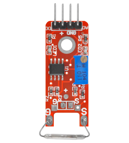
The Magnetic Module is a versatile electronic component that leverages magnetic fields to perform various functions, such as sensing, actuation, or energy conversion. It is commonly used in applications requiring magnetic field detection, proximity sensing, or motion control. This module is widely employed in robotics, automation systems, and consumer electronics due to its reliability and ease of integration.

Explore Projects Built with Magnetic Module

Use Cirkit Designer to design, explore, and prototype these projects online. Some projects support real-time simulation. Click "Open Project" to start designing instantly!
Arduino Uno R3 and HMC5883L Compass Interface
Image of Magnometer: A project utilizing Magnetic Module in a practical application
This circuit connects an HMC5883L compass module to an Arduino Uno R3 for the purpose of reading magnetic field data. The Arduino is programmed to initialize the compass module, continuously read its X, Y, and Z magnetometer data, and output the readings to the Serial Monitor. The compass module is interfaced with the Arduino via I2C communication, using the SDA and SCL lines, and powered through the Arduino's VIN pin.
Cirkit Designer LogoOpen Project in Cirkit Designer
Arduino Nano 33 BLE Magnetic Levitation System with Hall Sensor Feedback and Status LED Indicator
Image of LEVITRON: A project utilizing Magnetic Module in a practical application
This circuit is designed for a magnetic levitation system that uses a Hall sensor to detect magnetic field strength and a TIP120 transistor to control the current through a levitating coil. An Arduino Nano 33 BLE microcontroller reads the sensor and adjusts the coil current via PWM to maintain levitation, while an LED indicates the system's status. The circuit includes power management with 5V DC sources and protective components like diodes and resistors for current control and indication.
Cirkit Designer LogoOpen Project in Cirkit Designer
Arduino Nano Based GPS Tracker with GSM Communication and Accelerometer
Image of Circuit Aayush: A project utilizing Magnetic Module in a practical application
This circuit is designed for communication and location tracking purposes. It features an Arduino Nano interfaced with a SIM800L GSM module for cellular connectivity, a GPS NEO 6M module for obtaining geographical coordinates, and an AITrip ADXL335 GY-61 accelerometer for motion sensing. The LM2596 Step Down Module is used to regulate the power supply to the components.
Cirkit Designer LogoOpen Project in Cirkit Designer
Raspberry Pi Pico-Based Navigation Assistant with Bluetooth and GPS
Image of sat_dish: compass example: A project utilizing Magnetic Module in a practical application
This circuit features a Raspberry Pi Pico microcontroller interfaced with an HC-05 Bluetooth module for wireless communication, an HMC5883L compass module for magnetic field measurement, and a GPS NEO 6M module for location tracking. The Pico is configured to communicate with the HC-05 via serial connection (TX/RX), with the compass module via I2C (SCL/SDA), and with the GPS module via serial (TX/RX). Common power (VCC) and ground (GND) lines are shared among all modules, indicating a unified power system.
Cirkit Designer LogoOpen Project in Cirkit Designer

Explore Projects Built with Magnetic Module

Use Cirkit Designer to design, explore, and prototype these projects online. Some projects support real-time simulation. Click "Open Project" to start designing instantly!
Image of Magnometer: A project utilizing Magnetic Module in a practical application
Arduino Uno R3 and HMC5883L Compass Interface
This circuit connects an HMC5883L compass module to an Arduino Uno R3 for the purpose of reading magnetic field data. The Arduino is programmed to initialize the compass module, continuously read its X, Y, and Z magnetometer data, and output the readings to the Serial Monitor. The compass module is interfaced with the Arduino via I2C communication, using the SDA and SCL lines, and powered through the Arduino's VIN pin.
Cirkit Designer LogoOpen Project in Cirkit Designer
Image of LEVITRON: A project utilizing Magnetic Module in a practical application
Arduino Nano 33 BLE Magnetic Levitation System with Hall Sensor Feedback and Status LED Indicator
This circuit is designed for a magnetic levitation system that uses a Hall sensor to detect magnetic field strength and a TIP120 transistor to control the current through a levitating coil. An Arduino Nano 33 BLE microcontroller reads the sensor and adjusts the coil current via PWM to maintain levitation, while an LED indicates the system's status. The circuit includes power management with 5V DC sources and protective components like diodes and resistors for current control and indication.
Cirkit Designer LogoOpen Project in Cirkit Designer
Image of Circuit Aayush: A project utilizing Magnetic Module in a practical application
Arduino Nano Based GPS Tracker with GSM Communication and Accelerometer
This circuit is designed for communication and location tracking purposes. It features an Arduino Nano interfaced with a SIM800L GSM module for cellular connectivity, a GPS NEO 6M module for obtaining geographical coordinates, and an AITrip ADXL335 GY-61 accelerometer for motion sensing. The LM2596 Step Down Module is used to regulate the power supply to the components.
Cirkit Designer LogoOpen Project in Cirkit Designer
Image of sat_dish: compass example: A project utilizing Magnetic Module in a practical application
Raspberry Pi Pico-Based Navigation Assistant with Bluetooth and GPS
This circuit features a Raspberry Pi Pico microcontroller interfaced with an HC-05 Bluetooth module for wireless communication, an HMC5883L compass module for magnetic field measurement, and a GPS NEO 6M module for location tracking. The Pico is configured to communicate with the HC-05 via serial connection (TX/RX), with the compass module via I2C (SCL/SDA), and with the GPS module via serial (TX/RX). Common power (VCC) and ground (GND) lines are shared among all modules, indicating a unified power system.
Cirkit Designer LogoOpen Project in Cirkit Designer

Common Applications and Use Cases

  • Magnetic field detection and measurement
  • Proximity sensing in industrial and consumer devices
  • Position and motion control in robotics
  • Energy conversion in wireless charging systems
  • Security systems for detecting magnetic tampering

Technical Specifications

Below are the key technical details and pin configuration for the Magnetic Module:

Key Technical Details

  • Operating Voltage: 3.3V to 5V DC
  • Current Consumption: < 10mA
  • Output Type: Digital (High/Low) or Analog (depending on the model)
  • Sensing Range: 0 to 5 cm (varies by model)
  • Operating Temperature: -20°C to 85°C
  • Dimensions: 32mm x 14mm x 8mm (typical)

Pin Configuration and Descriptions

The Magnetic Module typically has three pins. The table below describes each pin:

Pin Name Description
1 VCC Power supply pin. Connect to 3.3V or 5V DC.
2 GND Ground pin. Connect to the ground of the circuit.
3 OUT Output pin. Provides a digital HIGH/LOW signal or an analog voltage (model-specific).

Usage Instructions

How to Use the Magnetic Module in a Circuit

  1. Power the Module: Connect the VCC pin to a 3.3V or 5V power source and the GND pin to the ground of your circuit.
  2. Connect the Output: Attach the OUT pin to a microcontroller's input pin (e.g., Arduino) or an external circuit to read the output signal.
  3. Place the Magnet: Position a magnet near the sensing area of the module. The module will detect the magnetic field and change its output accordingly.
    • For digital modules, the output will toggle between HIGH and LOW.
    • For analog modules, the output voltage will vary based on the magnetic field strength.

Important Considerations and Best Practices

  • Magnet Placement: Ensure the magnet is within the sensing range of the module for accurate detection.
  • Power Supply: Use a stable power source to avoid erratic behavior.
  • Interference: Avoid placing the module near strong electromagnetic sources, as they may interfere with its operation.
  • Orientation: The module's sensitivity may vary based on the orientation of the magnetic field. Test and adjust placement as needed.

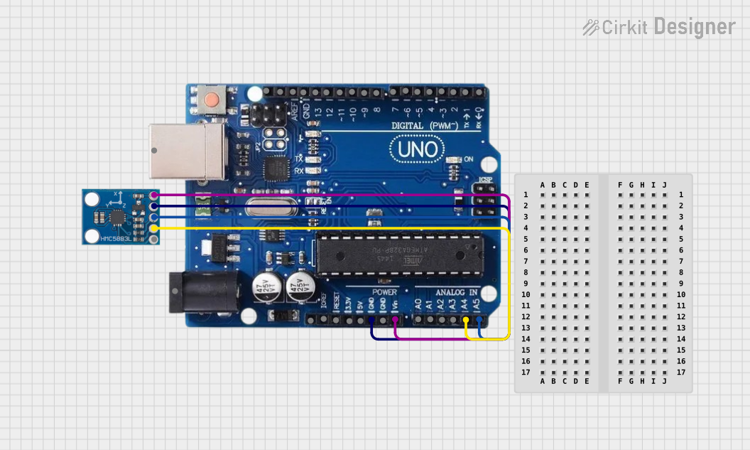
Example: Connecting to an Arduino UNO

Below is an example of how to use the Magnetic Module with an Arduino UNO to detect a magnetic field:

// Magnetic Module Example with Arduino UNO
// This code reads the digital output of the Magnetic Module and turns on an LED
// when a magnetic field is detected.

const int magneticPin = 2; // Connect the OUT pin of the module to digital pin 2
const int ledPin = 13;     // Built-in LED on Arduino UNO

void setup() {
  pinMode(magneticPin, INPUT); // Set the magnetic module pin as input
  pinMode(ledPin, OUTPUT);     // Set the LED pin as output
  Serial.begin(9600);          // Initialize serial communication for debugging
}

void loop() {
  int magneticState = digitalRead(magneticPin); // Read the module's output

  if (magneticState == HIGH) {
    // Magnetic field detected
    digitalWrite(ledPin, HIGH); // Turn on the LED
    Serial.println("Magnetic field detected!");
  } else {
    // No magnetic field detected
    digitalWrite(ledPin, LOW);  // Turn off the LED
    Serial.println("No magnetic field detected.");
  }

  delay(500); // Wait for 500ms before the next reading
}

Troubleshooting and FAQs

Common Issues and Solutions

  1. No Output Signal:

    • Cause: Incorrect wiring or loose connections.
    • Solution: Double-check the connections, ensuring VCC, GND, and OUT are properly connected.
  2. Erratic Output:

    • Cause: Unstable power supply or electromagnetic interference.
    • Solution: Use a regulated power source and keep the module away from strong electromagnetic sources.
  3. Low Sensitivity:

    • Cause: Magnet is too far from the module or improperly oriented.
    • Solution: Ensure the magnet is within the sensing range and adjust its orientation.
  4. Output Always HIGH or LOW:

    • Cause: Faulty module or incorrect placement of the magnet.
    • Solution: Test the module with a known good magnet and verify its functionality.

FAQs

Q1: Can the Magnetic Module detect all types of magnets?
A1: The module is designed to detect common permanent magnets (e.g., neodymium, ferrite). Its sensitivity may vary depending on the magnet's strength and size.

Q2: Can I use the Magnetic Module with a 12V power supply?
A2: No, the module is designed for 3.3V to 5V operation. Using a higher voltage may damage the module.

Q3: How do I know if the module is working?
A3: You can test the module by connecting it to an LED or a microcontroller. When a magnet is brought near, the output should change (e.g., LED turns on/off).

Q4: Is the module affected by temperature changes?
A4: The module operates reliably within its specified temperature range (-20°C to 85°C). Extreme temperatures may affect performance.