How to Use Stepper Motor Driver: Examples, Pinouts, and Specs
Introduction
A stepper motor driver is a device that controls the operation of a stepper motor by sending it precise electrical pulses. These pulses determine the motor's movement, allowing for accurate positioning and speed control. Stepper motor drivers are essential in applications requiring precise motion, such as 3D printers, CNC machines, robotics, and automated camera systems.
By managing the current and voltage supplied to the motor, the driver ensures smooth operation and prevents damage to the motor. It also simplifies the process of interfacing stepper motors with microcontrollers or other control systems.
Explore Projects Built with Stepper Motor Driver


Explore Projects Built with Stepper Motor Driver
Technical Specifications
Below are the general technical specifications for a typical stepper motor driver. Note that specific models may vary, so always refer to the datasheet of your particular driver.
General Specifications
- Input Voltage Range: 8V to 35V (varies by model)
- Output Current: Up to 2A per phase (adjustable via potentiometer)
- Microstepping Modes: Full step, half step, 1/4 step, 1/8 step, 1/16 step
- Control Interface: Step and direction pins
- Protection Features: Overcurrent, overtemperature, and undervoltage lockout
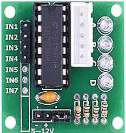
Pin Configuration and Descriptions
The following table describes the pinout for a common stepper motor driver, such as the A4988 or DRV8825:
| Pin Name | Description |
|---|---|
| VMOT | Motor power supply (8V to 35V). Connect to the motor's power source. |
| GND | Ground connection for both logic and motor power. |
| VDD | Logic power supply (3.3V or 5V, depending on the microcontroller). |
| STEP | Receives pulses to control the motor's steps. Each pulse moves the motor one step. |
| DIR | Sets the motor's rotation direction (high for one direction, low for the other). |
| ENABLE | Enables or disables the motor driver (active low). |
| MS1, MS2, MS3 | Microstepping mode selection pins. Configure for desired step resolution. |
| OUT1A, OUT1B | Connect to one coil of the stepper motor. |
| OUT2A, OUT2B | Connect to the other coil of the stepper motor. |
| RESET | Resets the driver (active low). |
| SLEEP | Puts the driver into low-power sleep mode (active low). |
Usage Instructions
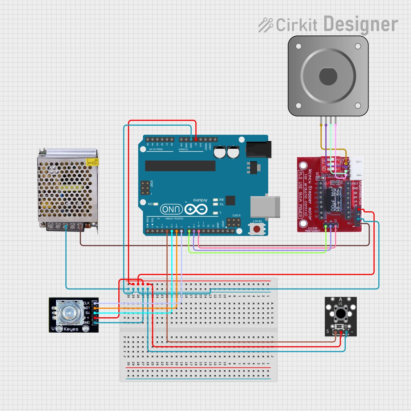
How to Use the Stepper Motor Driver in a Circuit
Power Connections:
- Connect the motor power supply to the VMOT pin and ground to the GND pin.
- Use a capacitor (e.g., 100µF) across VMOT and GND to filter noise and stabilize the power supply.
- Connect the logic power supply (3.3V or 5V) to the VDD pin.
Motor Connections:
- Identify the two coils of your stepper motor using a multimeter.
- Connect one coil to OUT1A and OUT1B, and the other coil to OUT2A and OUT2B.
Control Connections:
- Connect the STEP and DIR pins to the corresponding GPIO pins on your microcontroller.
- Optionally, connect the ENABLE pin to a GPIO pin for motor enable/disable control.
Microstepping Configuration:
- Use the MS1, MS2, and MS3 pins to set the desired microstepping mode. Refer to the driver datasheet for the configuration table.
Adjust Current Limit:
- Use the onboard potentiometer to set the current limit based on your motor's specifications. This prevents overheating and ensures optimal performance.
Arduino UNO Example Code
Below is an example of how to control a stepper motor driver using an Arduino UNO:
// Define pin connections
#define STEP_PIN 3  // Pin connected to STEP on the driver
#define DIR_PIN 4   // Pin connected to DIR on the driver

void setup() {
  pinMode(STEP_PIN, OUTPUT); // Set STEP pin as output
  pinMode(DIR_PIN, OUTPUT);  // Set DIR pin as output

  digitalWrite(DIR_PIN, HIGH); // Set initial direction (HIGH or LOW)
}

void loop() {
  // Generate a pulse to move the motor one step
  digitalWrite(STEP_PIN, HIGH); // Set STEP pin HIGH
  delayMicroseconds(500);       // Wait for 500 microseconds
  digitalWrite(STEP_PIN, LOW);  // Set STEP pin LOW
  delayMicroseconds(500);       // Wait for 500 microseconds

  // Repeat to create continuous motion
}
Important Considerations and Best Practices
- Always set the current limit on the driver to match your motor's rated current.
- Use a heatsink or cooling fan if the driver gets too hot during operation.
- Avoid disconnecting the motor while the driver is powered, as this can damage the driver.
- Ensure proper decoupling capacitors are used to stabilize the power supply.
Troubleshooting and FAQs
Common Issues and Solutions
Motor Not Moving:
- Check all connections, especially the motor coils and power supply.
- Verify that the STEP pin is receiving pulses from the microcontroller.
Motor Vibrates but Doesn't Rotate:
- Ensure the DIR pin is set correctly for the desired direction.
- Check the microstepping configuration and adjust if necessary.
Driver Overheating:
- Reduce the current limit using the potentiometer.
- Add a heatsink or cooling fan to the driver.
Motor Skipping Steps:
- Increase the pulse frequency gradually to avoid missing steps.
- Ensure the power supply can provide sufficient current for the motor.
FAQs
Q: Can I use a stepper motor driver with a 6-wire or 8-wire stepper motor?
A: Yes, but you need to configure the motor as a 4-wire bipolar stepper by identifying and connecting the appropriate coil pairs.
Q: How do I calculate the required pulse frequency for my motor?
A: The pulse frequency depends on the motor's step angle and desired speed. Use the formula:
Frequency (Hz) = (Steps per Revolution × RPM) / 60.
Q: Can I control multiple stepper motors with one Arduino?
A: Yes, but each motor will require its own driver, and you must assign separate STEP and DIR pins for each driver.
By following this documentation, you can effectively use a stepper motor driver in your projects for precise motion control.