How to Use BC 337 NPN Transistor: Examples, Pinouts, and Specs

Introduction
The BC337 is a small-signal NPN bipolar junction transistor (BJT) manufactured by Onsemi. It is widely used in amplification and switching applications due to its ability to handle moderate current and voltage levels. This versatile transistor is ideal for low-power audio amplifiers, signal processing circuits, and general-purpose switching tasks in electronic projects.
Explore Projects Built with BC 337 NPN Transistor

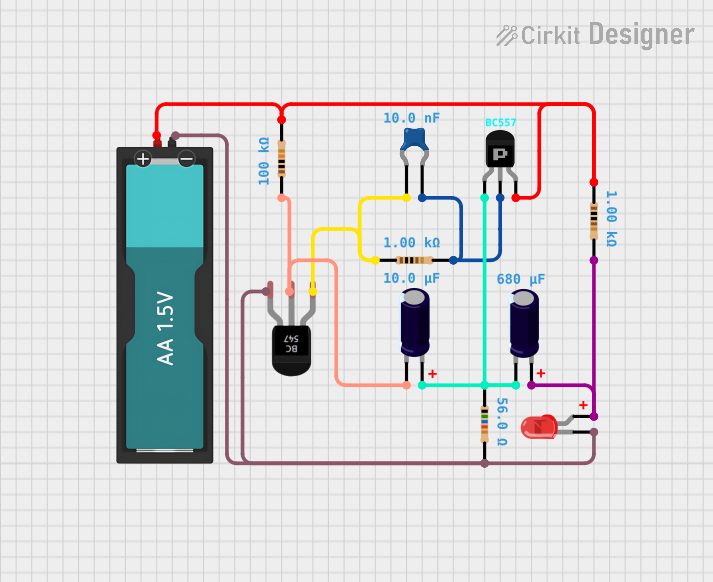
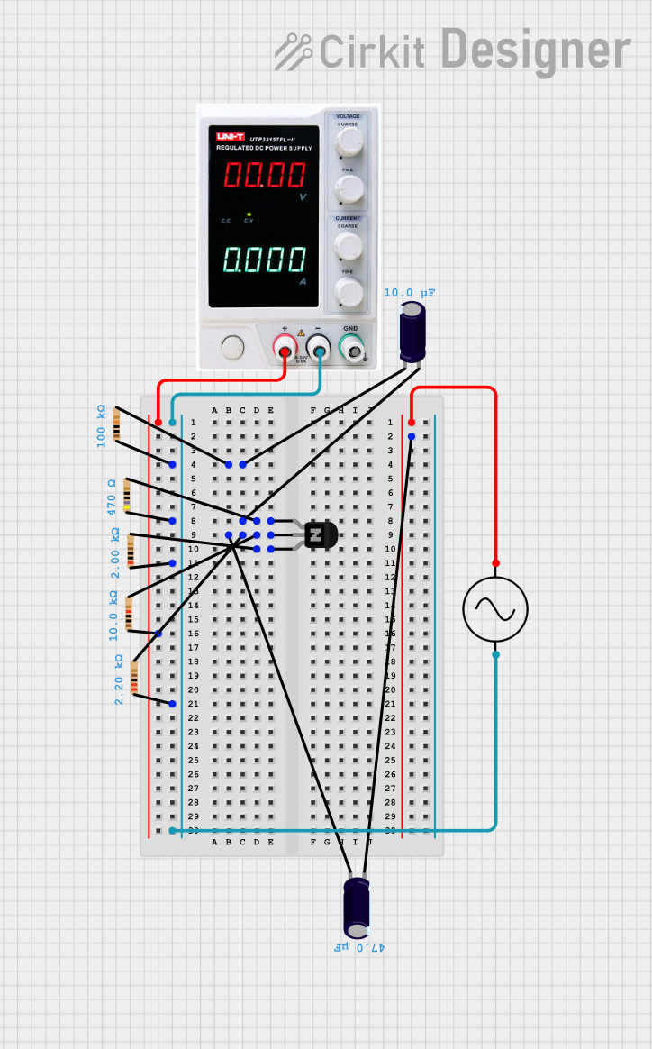
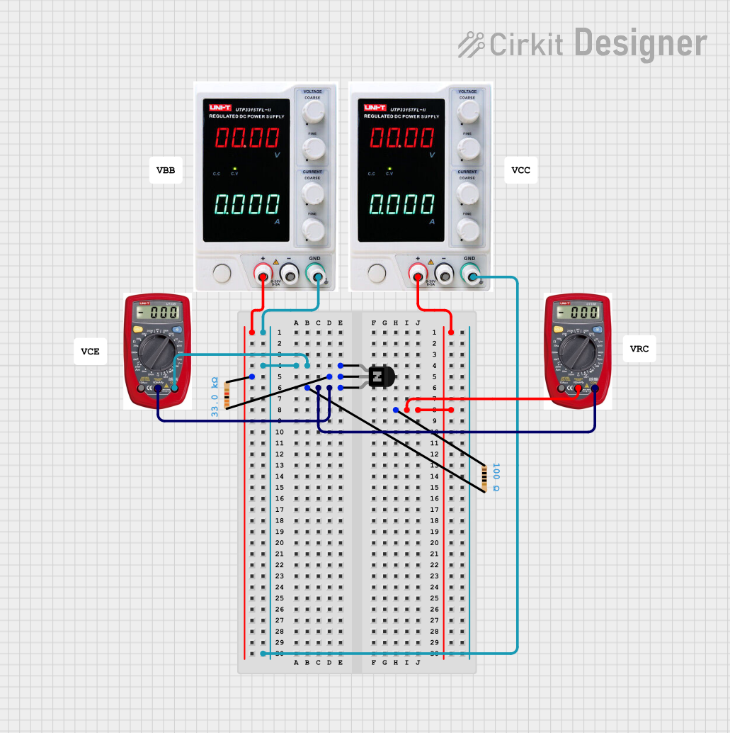
Explore Projects Built with BC 337 NPN Transistor
Common Applications
- Audio signal amplification
- Low-power switching circuits
- LED drivers
- Small motor control
- General-purpose signal processing
Technical Specifications
The BC337 transistor is designed to operate efficiently in a variety of electronic circuits. Below are its key technical specifications:
| Parameter | Value |
|---|---|
| Manufacturer | Onsemi |
| Transistor Type | NPN |
| Maximum Collector Current (Ic) | 800 mA |
| Maximum Collector-Emitter Voltage (Vce) | 45 V |
| Maximum Collector-Base Voltage (Vcb) | 50 V |
| Maximum Emitter-Base Voltage (Veb) | 5 V |
| DC Current Gain (hFE) | 100 to 630 (varies by model) |
| Power Dissipation (Ptot) | 625 mW |
| Transition Frequency (fT) | 100 MHz |
| Package Type | TO-92 |
| Operating Temperature Range | -55°C to +150°C |
Pin Configuration
The BC337 transistor comes in a TO-92 package with three pins. The pinout is as follows:
| Pin Number | Pin Name | Description |
|---|---|---|
| 1 | Collector | Current flows into this pin. |
| 2 | Base | Controls the transistor's state. |
| 3 | Emitter | Current flows out of this pin. |
The pin configuration is shown below (viewed from the flat side of the TO-92 package):
   _______
  |       |
  |       |
  |_______|
   | | |
   1 2 3
   C B E
Usage Instructions
The BC337 transistor can be used in a variety of circuits for amplification and switching. Below are guidelines for its proper usage:
Using the BC337 in a Circuit
- Determine the Operating Region: The BC337 operates in three regions:
- Cutoff Region: The transistor is OFF (no current flows from collector to emitter).
- Active Region: The transistor amplifies the input signal.
- Saturation Region: The transistor is fully ON, acting as a closed switch.
- Base Resistor Selection: To control the transistor, calculate the base resistor (Rb) using the formula:
[
R_b = \frac{V_{in} - V_{be}}{I_b}
]
Where:
- ( V_{in} ) is the input voltage.
- ( V_{be} ) is the base-emitter voltage (typically 0.7 V for the BC337).
- ( I_b ) is the base current, which can be approximated as ( I_c / h_{FE} ).
- Connect the Pins: Ensure the collector, base, and emitter are connected correctly in the circuit.
Example: Driving an LED with the BC337
The following example demonstrates how to use the BC337 to drive an LED with an Arduino UNO.
Circuit Diagram
- Collector: Connect to the LED's anode (via a current-limiting resistor).
- Base: Connect to an Arduino digital pin (via a base resistor).
- Emitter: Connect to ground.
Arduino Code
// Define the pin connected to the BC337 base
const int transistorBasePin = 9; // Digital pin 9

void setup() {
  pinMode(transistorBasePin, OUTPUT); // Set the pin as an output
}

void loop() {
  digitalWrite(transistorBasePin, HIGH); // Turn the LED ON
  delay(1000); // Wait for 1 second
  digitalWrite(transistorBasePin, LOW);  // Turn the LED OFF
  delay(1000); // Wait for 1 second
}
Important Considerations
- Heat Dissipation: Ensure the transistor does not exceed its maximum power dissipation (625 mW). Use a heatsink if necessary.
- Voltage Ratings: Do not exceed the maximum voltage ratings for Vce, Vcb, or Veb.
- Current Ratings: Avoid exceeding the maximum collector current (800 mA) to prevent damage.
Troubleshooting and FAQs
Common Issues
Transistor Not Switching Properly
- Cause: Insufficient base current or incorrect base resistor value.
- Solution: Recalculate the base resistor to ensure adequate base current.
Excessive Heat
- Cause: The transistor is operating near or beyond its power dissipation limit.
- Solution: Reduce the load current or use a heatsink.
No Output Signal
- Cause: Incorrect pin connections or damaged transistor.
- Solution: Verify the pin connections and replace the transistor if necessary.
LED Not Lighting Up
- Cause: Incorrect resistor value or insufficient base drive.
- Solution: Check the current-limiting resistor and base resistor values.
FAQs
Q1: Can the BC337 be used for high-frequency applications?
A1: Yes, the BC337 has a transition frequency (fT) of 100 MHz, making it suitable for moderate high-frequency applications.
Q2: What is the maximum current the BC337 can handle?
A2: The BC337 can handle a maximum collector current of 800 mA.
Q3: Can I use the BC337 to drive a motor?
A3: Yes, the BC337 can drive small DC motors, provided the current does not exceed 800 mA.
Q4: How do I test if my BC337 is working?
A4: Use a multimeter in diode mode to check the base-emitter and base-collector junctions. A forward voltage drop of ~0.7 V indicates a functional transistor.
By following this documentation, you can effectively use the BC337 transistor in your electronic projects.