How to Use Adafruit 7 Segment FeatherWing - Red: Examples, Pinouts, and Specs
Introduction
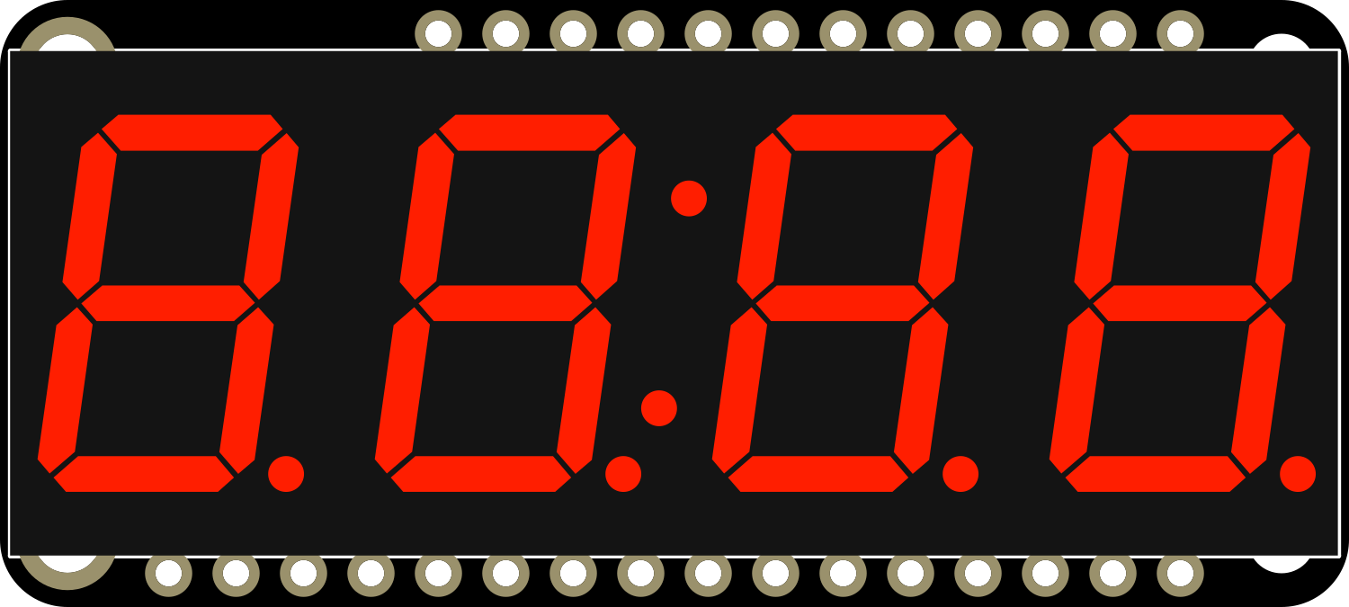
The Adafruit 7 Segment FeatherWing - Red is a versatile and user-friendly electronic component designed to display numerical information in a clear and readable format. This component features a bright red 4-digit, 7-segment LED display, which can show numbers, some letters, and a few special characters. It is commonly used in digital clocks, timers, counters, and other projects where numerical data needs to be presented to the user.
Explore Projects Built with Adafruit 7 Segment FeatherWing - Red
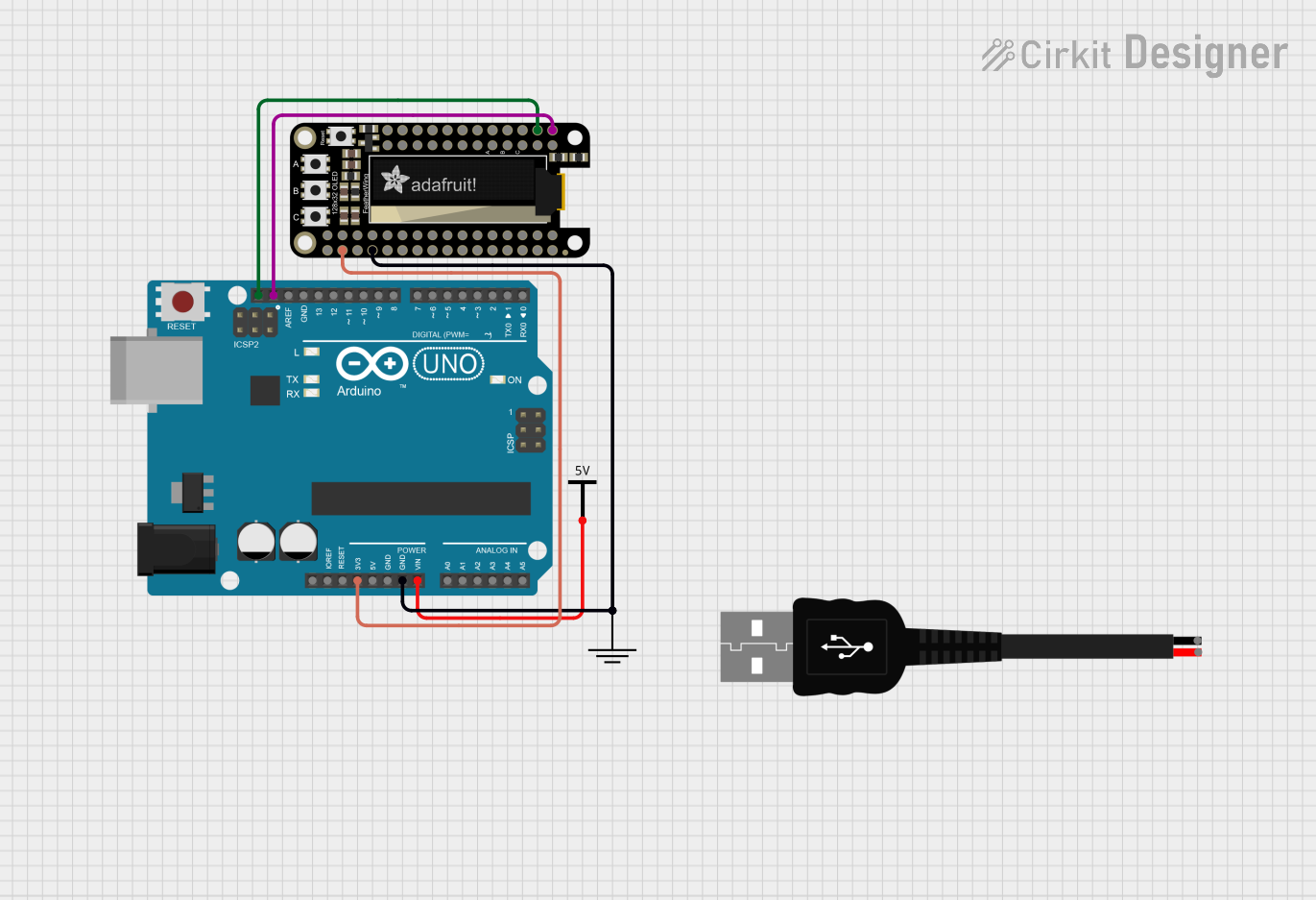

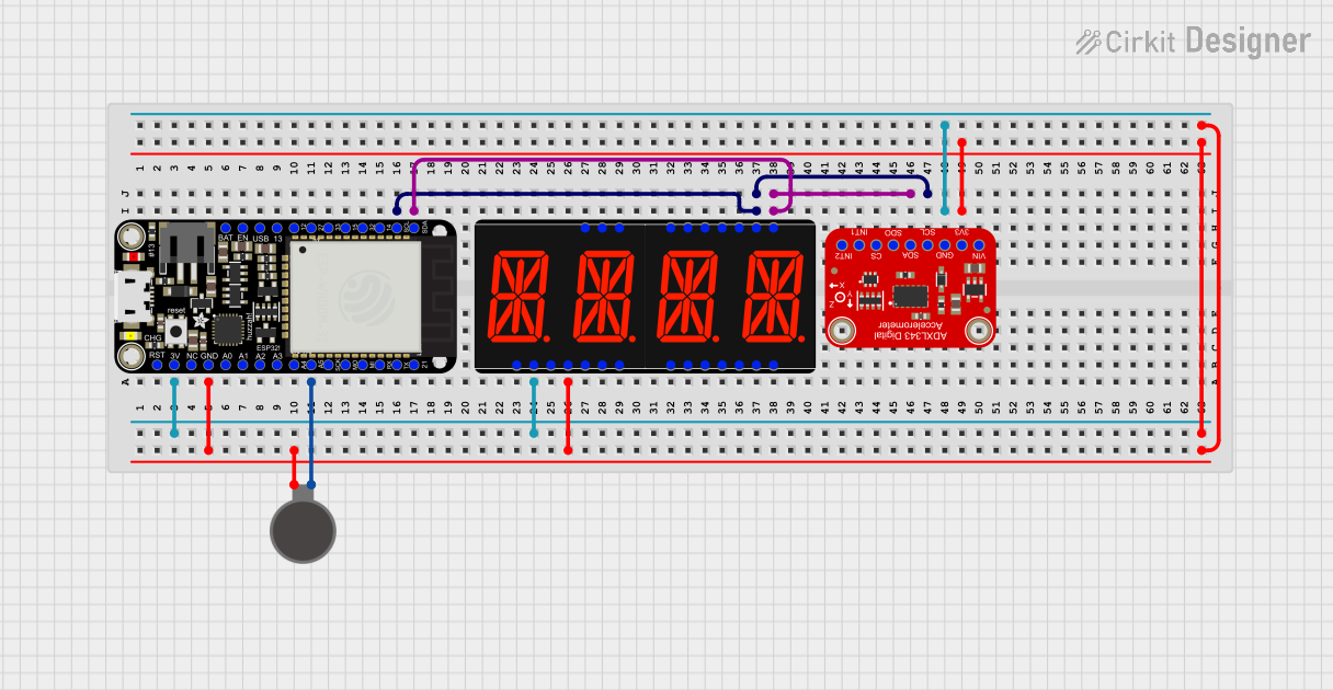
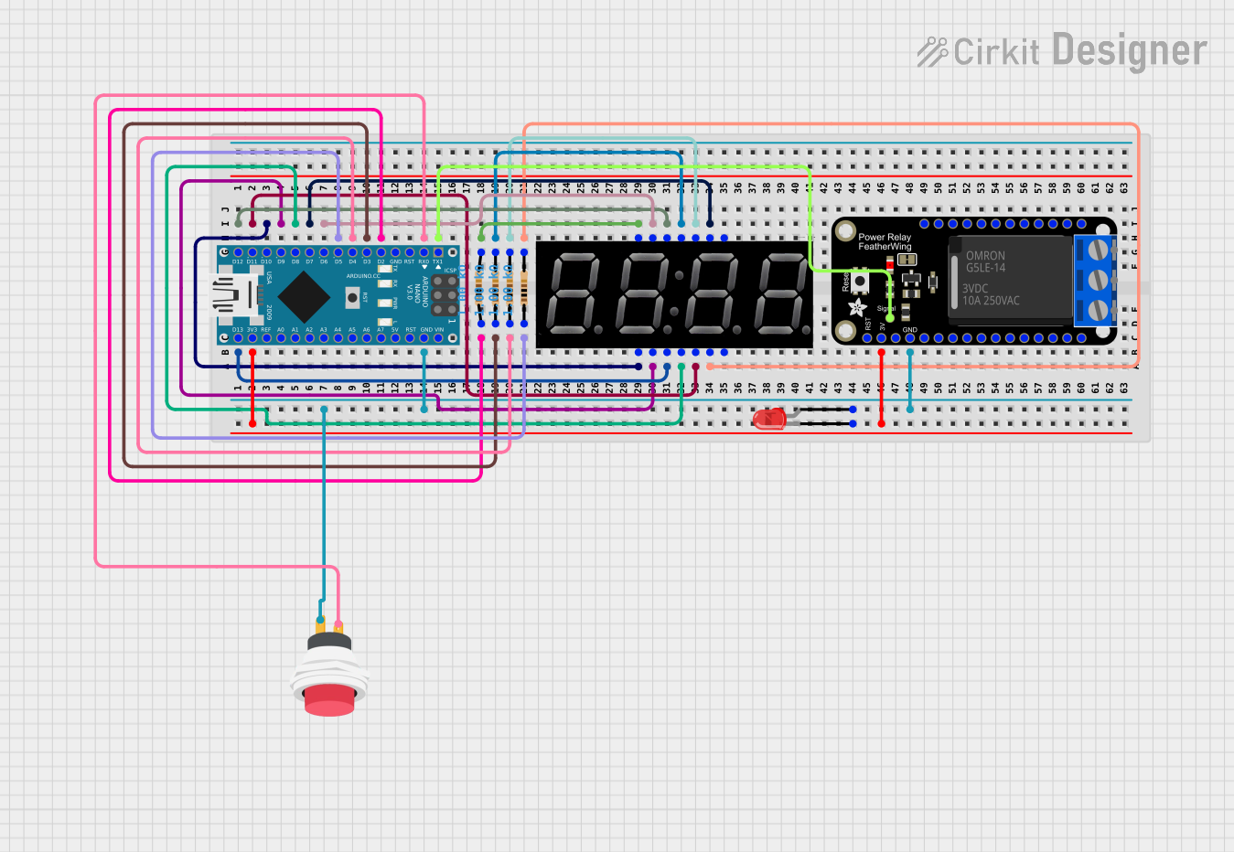
Explore Projects Built with Adafruit 7 Segment FeatherWing - Red
Common Applications and Use Cases
- Digital clocks and timers
- Counters and scoreboards
- Temperature displays
- Simple calculators
- Battery level indicators
Technical Specifications
Key Technical Details
- Display Color: Red
- Number of Digits: 4
- Common Anode/Cathode: Common Anode
- Operating Voltage: 3.3V to 5V
- Interface: I2C
- I2C Addresses: 0x70 (default), selectable with solder jumpers
Pin Configuration and Descriptions
| Pin | Description |
|---|---|
| GND | Ground connection |
| 3V | 3.3V power supply |
| SDA | I2C data line |
| SCL | I2C clock line |
| RST | Reset pin (optional) |
Usage Instructions
How to Use the Component in a Circuit
- Powering the Display: Connect the 3V pin to a 3.3V power supply and the GND pin to the ground on your microcontroller board.
- I2C Communication: Connect the SDA and SCL pins to the corresponding I2C data and clock lines on your microcontroller.
- Address Selection: If using multiple displays, adjust the I2C address using the solder jumpers on the back of the FeatherWing.
Important Considerations and Best Practices
- Ensure that the power supply voltage matches the operating voltage of the FeatherWing to prevent damage.
- Use pull-up resistors on the I2C lines if they are not already present on the microcontroller board.
- When stacking multiple FeatherWings, ensure that each has a unique I2C address.
- Avoid exposing the display to direct sunlight for extended periods to prevent fading.
Example Code for Arduino UNO
#include <Wire.h>
#include <Adafruit_LEDBackpack.h>
#include <Adafruit_GFX.h>

Adafruit_7segment matrix = Adafruit_7segment();

void setup() {
  matrix.begin(0x70); // Initialize the display with its I2C address
}

void loop() {
  matrix.print(1234, DEC); // Display the number 1234
  matrix.writeDisplay();    // Refresh the display with new data
  delay(5000);             // Wait for 5 seconds

  // Display a hexadecimal number
  matrix.print(0xBEEF, HEX);
  matrix.writeDisplay();
  delay(5000);
}
Note: This example assumes that the Adafruit LED Backpack library is installed in your Arduino IDE.
Troubleshooting and FAQs
Common Issues
- Display Not Lighting Up: Check the power connections and ensure the I2C lines are properly connected.
- Garbled or Incorrect Display: Verify that the I2C address is correctly set and that there are no conflicts with other devices on the I2C bus.
- Dim Display: Ensure that the power supply is providing sufficient voltage and current.
Solutions and Tips for Troubleshooting
- Double-check wiring connections for any loose or incorrect connections.
- Use the
i2cdetectutility or similar tools to confirm the device's address on the I2C bus. - If using multiple displays, ensure each has a unique I2C address by adjusting the solder jumpers.
FAQs
Q: Can I use this display with a 5V microcontroller? A: Yes, the display can be used with a 5V microcontroller, but ensure that the logic levels for I2C communication are compatible.
Q: How do I change the brightness of the display?
A: The brightness can be adjusted using the setBrightness(uint8_t b) function provided by the Adafruit LED Backpack library.
Q: Can I display letters as well as numbers? A: Yes, the display can show some letters and special characters that can be formed with 7 segments.
Q: How many of these displays can I chain together? A: You can chain up to 8 displays by setting unique I2C addresses using the solder jumpers on the back of each FeatherWing.
For further assistance, refer to the Adafruit support forums or the product's official documentation.