How to Use NUC-UPS: Examples, Pinouts, and Specs
Introduction
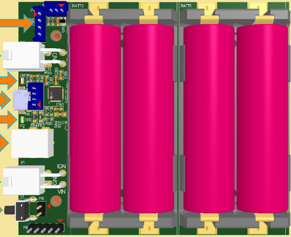
The NUC-UPS (Uninterruptible Power Supply) by Mini-Box is a compact and efficient power backup solution designed specifically for Intel NUC (Next Unit of Computing) systems. It ensures uninterrupted power delivery during outages, safeguarding data integrity and preventing system crashes. With its small form factor and intelligent power management features, the NUC-UPS is ideal for applications requiring reliable power, such as home servers, IoT devices, and industrial automation systems.
Explore Projects Built with NUC-UPS


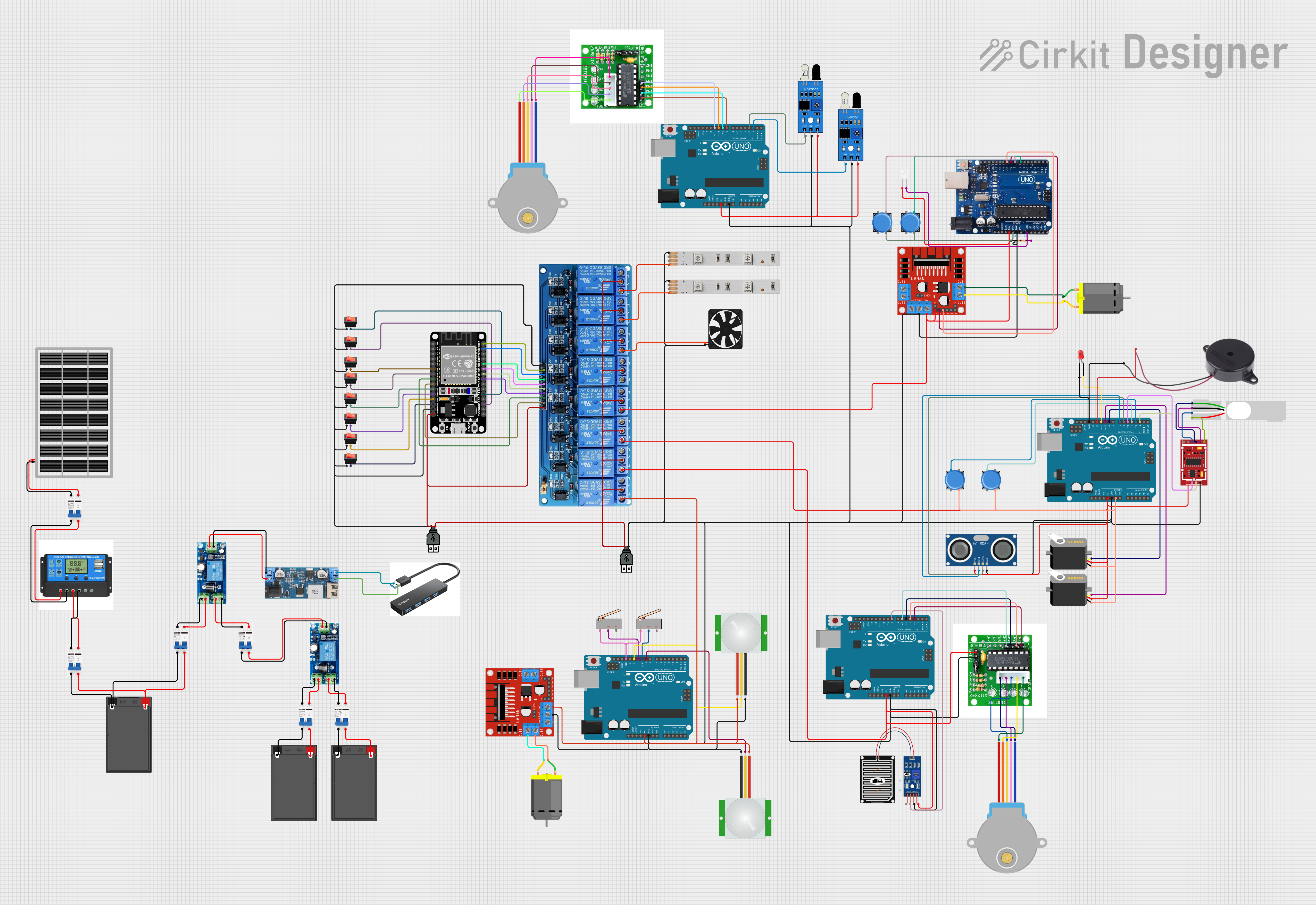
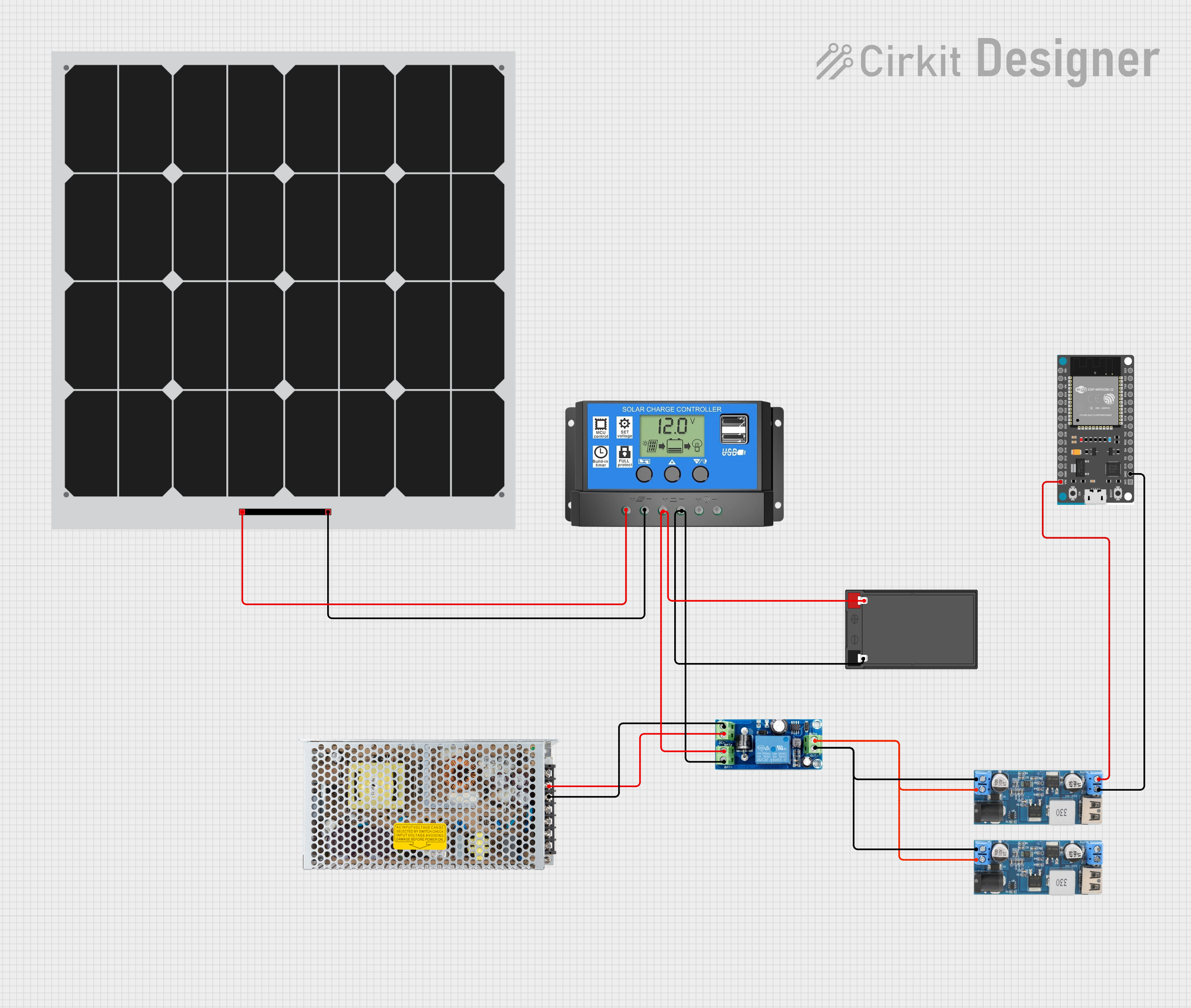
Explore Projects Built with NUC-UPS
Common Applications and Use Cases
- Home Servers: Ensures continuous operation of Intel NUC-based home servers during power outages.
- IoT Devices: Provides reliable power for IoT hubs and gateways.
- Industrial Automation: Maintains uninterrupted operation of NUC systems in industrial environments.
- Edge Computing: Supports edge devices requiring stable power in remote or unstable power conditions.
- Data Integrity: Prevents data loss and corruption during unexpected power failures.
Technical Specifications
Key Technical Details
| Parameter | Value |
|---|---|
| Input Voltage Range | 12V to 19V DC |
| Output Voltage | 12V DC (regulated) |
| Maximum Output Current | 6A |
| Battery Type | Lithium Polymer (LiPo) |
| Battery Capacity | 2,300mAh (default, expandable with external batteries) |
| Charging Current | 1A to 2A (configurable) |
| Backup Time | Up to 2 hours (depending on load and battery capacity) |
| Dimensions | 96mm x 60mm x 22mm |
| Operating Temperature Range | 0°C to 50°C |
| Communication Interface | I2C and UART for monitoring and control |
| Protection Features | Overvoltage, undervoltage, overcurrent, and short-circuit protection |
Pin Configuration and Descriptions
The NUC-UPS features a set of connectors for power input, output, and communication. Below is the pin configuration:
Power Input/Output Connector
| Pin | Name | Description |
|---|---|---|
| 1 | VIN+ | Positive input voltage (12V to 19V DC) |
| 2 | VIN- | Ground for input voltage |
| 3 | VOUT+ | Positive regulated output voltage (12V DC) |
| 4 | VOUT- | Ground for output voltage |
Communication Interface (I2C/UART)
| Pin | Name | Description |
|---|---|---|
| 1 | SDA | I2C data line |
| 2 | SCL | I2C clock line |
| 3 | TX | UART transmit line |
| 4 | RX | UART receive line |
| 5 | GND | Ground for communication lines |
Usage Instructions
How to Use the NUC-UPS in a Circuit
- Connect Power Input:
- Attach a DC power adapter (12V to 19V) to the VIN+ and VIN- pins.
- Connect Power Output:
- Connect the VOUT+ and VOUT- pins to the Intel NUC's power input.
- Battery Connection (Optional):
- If using an external battery, connect it to the designated battery connector.
- Communication Interface (Optional):
- For monitoring and control, connect the I2C or UART pins to a microcontroller or computer.
Important Considerations and Best Practices
- Battery Selection: Use only compatible LiPo batteries with the correct voltage and capacity ratings.
- Ventilation: Ensure proper ventilation to prevent overheating during operation.
- Load Capacity: Do not exceed the maximum output current of 6A to avoid damage.
- Firmware Updates: Check for firmware updates from Mini-Box to ensure optimal performance.
- Monitoring: Use the I2C or UART interface to monitor battery status, input/output voltage, and other parameters.
Example: Connecting NUC-UPS to an Arduino UNO
The NUC-UPS can be monitored using an Arduino UNO via the I2C interface. Below is an example code snippet:
#include <Wire.h> // Include the Wire library for I2C communication

#define NUC_UPS_I2C_ADDRESS 0x40 // Default I2C address of the NUC-UPS

void setup() {
  Wire.begin(); // Initialize I2C communication
  Serial.begin(9600); // Initialize serial communication for debugging
  Serial.println("NUC-UPS Monitoring Started");
}

void loop() {
  Wire.beginTransmission(NUC_UPS_I2C_ADDRESS); // Start communication with NUC-UPS
  Wire.write(0x01); // Request battery status register (example register address)
  Wire.endTransmission();

  Wire.requestFrom(NUC_UPS_I2C_ADDRESS, 1); // Request 1 byte of data
  if (Wire.available()) {
    uint8_t batteryStatus = Wire.read(); // Read the battery status
    Serial.print("Battery Status: ");
    Serial.println(batteryStatus, HEX); // Print the status in hexadecimal
  }

  delay(1000); // Wait for 1 second before the next reading
}
Troubleshooting and FAQs
Common Issues and Solutions
NUC-UPS Not Powering the NUC System
- Cause: Incorrect input voltage or loose connections.
- Solution: Verify that the input voltage is within the 12V to 19V range and check all connections.
Battery Not Charging
- Cause: Faulty battery or incorrect charging current configuration.
- Solution: Ensure the battery is compatible and check the charging current settings.
Overheating
- Cause: Insufficient ventilation or excessive load.
- Solution: Improve ventilation and ensure the load does not exceed 6A.
Communication Interface Not Working
- Cause: Incorrect wiring or I2C address mismatch.
- Solution: Verify the wiring and ensure the correct I2C address is used in the code.
FAQs
Q: Can I use the NUC-UPS with devices other than Intel NUC?
A: Yes, as long as the device operates within the 12V DC output range and does not exceed 6A.Q: How do I expand the battery capacity?
A: Connect an external LiPo battery with a compatible voltage and capacity to the battery connector.Q: Does the NUC-UPS support hot-swapping of batteries?
A: No, it is recommended to power down the system before replacing the battery.Q: Can I monitor the NUC-UPS remotely?
A: Yes, use the I2C or UART interface to monitor parameters such as battery status and voltage.
This concludes the documentation for the NUC-UPS by Mini-Box. For further assistance, refer to the manufacturer's user manual or contact their support team.