Cirkit Designer Logo
Cirkit Designer
Your all-in-one circuit design IDE
Home / 
Component Documentation

How to Use 3.5mm Audio Jack 3 Pin: Examples, Pinouts, and Specs

Image of 3.5mm Audio Jack 3 Pin
Cirkit Designer LogoDesign with 3.5mm Audio Jack 3 Pin in Cirkit Designer

Introduction

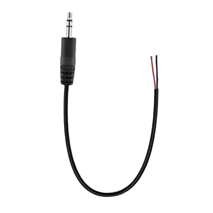
The 3.5mm Audio Jack 3 Pin, commonly referred to as a TRS (Tip, Ring, Sleeve) connector, is a widely used audio connector in various electronic devices. It is designed to carry audio signals for applications such as headphones, earphones, microphones, and auxiliary connections in vehicles and home audio systems.

Explore Projects Built with 3.5mm Audio Jack 3 Pin

Use Cirkit Designer to design, explore, and prototype these projects online. Some projects support real-time simulation. Click "Open Project" to start designing instantly!
Audio Signal Routing with TRRS 3.5mm Jack Breakouts
Image of 3.5mm 1W 8Ohm Speaker: A project utilizing 3.5mm Audio Jack 3 Pin in a practical application
This circuit is designed to interface two TRRS 3.5mm audio jacks with a standard 3.5mm audio jack, routing audio signals between them. The microcontroller present in the circuit does not have an active role as the provided code is empty.
Cirkit Designer LogoOpen Project in Cirkit Designer
Audio Signal Conditioning Circuit with 3.5mm Jacks and Passive Components
Image of BA: A project utilizing 3.5mm Audio Jack 3 Pin in a practical application
This circuit appears to be an audio signal processing or filtering circuit, utilizing multiple 3.5mm jacks for input and output connections, resistors, and capacitors to form various RC (resistor-capacitor) networks. The configuration suggests it could be used for tasks such as audio signal conditioning, noise filtering, or impedance matching.
Cirkit Designer LogoOpen Project in Cirkit Designer
PAM8403 Amplifier with 3.5mm Audio Jack for Mono Speaker Output
Image of 3.5mm 1W 8Ohm Speaker: A project utilizing 3.5mm Audio Jack 3 Pin in a practical application
This circuit is a mono audio amplifier system. It uses a PAM8403 amplifier IC to amplify the audio signal received from a 3.5mm audio jack and drives a speaker. The audio signal from the left channel (L) of the audio jack is amplified and output through the speaker, while the right channel (R) is connected but not utilized in this mono setup.
Cirkit Designer LogoOpen Project in Cirkit Designer
Arduino UNO and DFPlayer Mini Audio Playback System with Button Control
Image of dfp player: A project utilizing 3.5mm Audio Jack 3 Pin in a practical application
This circuit is a simple audio playback system controlled by an Arduino UNO. It uses a DFPlayer Mini to play audio files from an SD card, which are output through a TRRS 3.5mm jack. A button connected to the Arduino triggers the playback of the first audio file when pressed.
Cirkit Designer LogoOpen Project in Cirkit Designer

Explore Projects Built with 3.5mm Audio Jack 3 Pin

Use Cirkit Designer to design, explore, and prototype these projects online. Some projects support real-time simulation. Click "Open Project" to start designing instantly!
Image of 3.5mm 1W 8Ohm Speaker: A project utilizing 3.5mm Audio Jack 3 Pin in a practical application
Audio Signal Routing with TRRS 3.5mm Jack Breakouts
This circuit is designed to interface two TRRS 3.5mm audio jacks with a standard 3.5mm audio jack, routing audio signals between them. The microcontroller present in the circuit does not have an active role as the provided code is empty.
Cirkit Designer LogoOpen Project in Cirkit Designer
Image of BA: A project utilizing 3.5mm Audio Jack 3 Pin in a practical application
Audio Signal Conditioning Circuit with 3.5mm Jacks and Passive Components
This circuit appears to be an audio signal processing or filtering circuit, utilizing multiple 3.5mm jacks for input and output connections, resistors, and capacitors to form various RC (resistor-capacitor) networks. The configuration suggests it could be used for tasks such as audio signal conditioning, noise filtering, or impedance matching.
Cirkit Designer LogoOpen Project in Cirkit Designer
Image of 3.5mm 1W 8Ohm Speaker: A project utilizing 3.5mm Audio Jack 3 Pin in a practical application
PAM8403 Amplifier with 3.5mm Audio Jack for Mono Speaker Output
This circuit is a mono audio amplifier system. It uses a PAM8403 amplifier IC to amplify the audio signal received from a 3.5mm audio jack and drives a speaker. The audio signal from the left channel (L) of the audio jack is amplified and output through the speaker, while the right channel (R) is connected but not utilized in this mono setup.
Cirkit Designer LogoOpen Project in Cirkit Designer
Image of dfp player: A project utilizing 3.5mm Audio Jack 3 Pin in a practical application
Arduino UNO and DFPlayer Mini Audio Playback System with Button Control
This circuit is a simple audio playback system controlled by an Arduino UNO. It uses a DFPlayer Mini to play audio files from an SD card, which are output through a TRRS 3.5mm jack. A button connected to the Arduino triggers the playback of the first audio file when pressed.
Cirkit Designer LogoOpen Project in Cirkit Designer

Common Applications and Use Cases

  • Personal audio devices (MP3 players, mobile phones, tablets)
  • Home audio systems (speakers, amplifiers)
  • Professional audio equipment (mixers, audio interfaces)
  • Computer audio (sound cards, speakers)
  • In-car auxiliary ports

Technical Specifications

Key Technical Details

  • Connector Type: 3.5mm TRS (Tip, Ring, Sleeve)
  • Number of Pins: 3
  • Contact Material: Typically brass with nickel or gold plating
  • Insulation Material: Plastic or rubber for external insulation
  • Rated Voltage: Typically up to 24V (peak)
  • Rated Current: Typically up to 0.5A

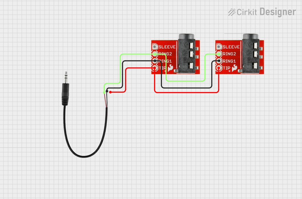
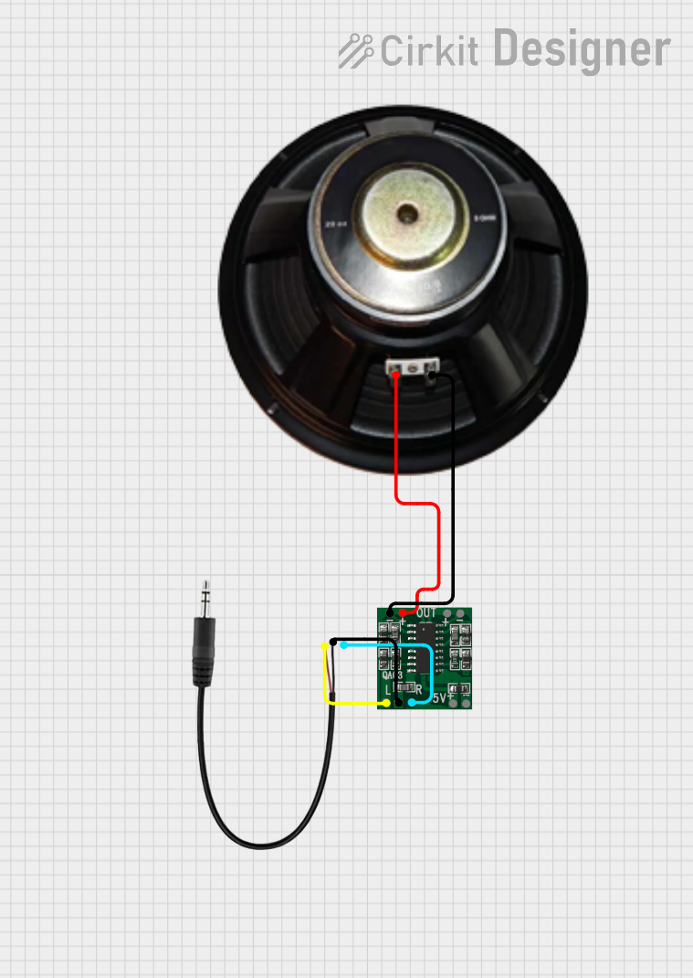
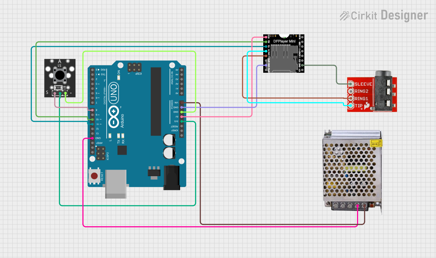
Pin Configuration and Descriptions

Pin Number Name Description
1 Tip Carries the left audio channel signal in stereo applications or the audio signal in mono applications.
2 Ring Carries the right audio channel signal in stereo applications.
3 Sleeve Common ground reference for the audio signals.

Usage Instructions

How to Use the Component in a Circuit

  1. Identify the Pins: Locate the tip, ring, and sleeve contacts on the audio jack.
  2. Soldering: Solder the appropriate wires to the corresponding pins. Use a low wattage soldering iron to avoid damaging the jack.
  3. Connection: Connect the left audio channel to the tip, the right audio channel to the ring, and the ground wire to the sleeve.
  4. Insulation: Ensure that the connections are insulated to prevent short circuits.
  5. Testing: Before powering up the circuit, test the connections with a multimeter to ensure there are no shorts.

Important Considerations and Best Practices

  • Strain Relief: Provide strain relief for the cables connected to the audio jack to prevent mechanical stress on the solder joints.
  • Signal Integrity: Use shielded cables for audio connections to minimize interference and maintain signal integrity.
  • Mounting: If the audio jack is panel-mounted, ensure a secure fit to prevent movement that could cause intermittent connections.

Troubleshooting and FAQs

Common Issues Users Might Face

  • Loose Connections: If audio is intermittent or absent, check for loose solder joints or broken wires.
  • Crossed Wires: Ensure that the left and right channels are not accidentally crossed.
  • Short Circuits: If there is no sound or distortion, check for shorts between the pins with a multimeter.

Solutions and Tips for Troubleshooting

  • Resoldering: If a connection is loose, resolder the wire to the appropriate pin.
  • Wire Identification: Use a multimeter's continuity function to trace and verify the correct wiring.
  • Inspection: Visually inspect the jack for any signs of damage or wear that could affect performance.

FAQs

Q: Can I use this audio jack for a mono application? A: Yes, you can use the tip for the audio signal and the sleeve for ground.

Q: What is the best way to solder wires to the audio jack? A: Use a low wattage soldering iron, apply a small amount of solder to the pin, and then heat the pin and wire together to form a solid joint.

Q: How can I prevent audio interference? A: Use shielded cables and ensure that the audio jack is properly grounded.

Note: This documentation is for a generic 3.5mm Audio Jack 3 Pin with the part ID "Jack" by a manufacturer named "Nobody." The specifications and instructions provided are based on common standards for this type of component and may vary for a specific manufacturer's part. Always consult the manufacturer's datasheet for precise information.