
How to Use Mini Digital Volt/Ammeter: Examples, Pinouts, and Specs
 Design with Mini Digital Volt/Ammeter in Cirkit Designer
Introduction
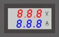
The Mini Digital Volt/Ammeter is a compact and versatile device designed to measure voltage and current in electrical circuits. It features a digital display for clear and accurate readings, making it an essential tool for hobbyists, engineers, and technicians. This component is widely used in applications such as power supply monitoring, battery testing, and circuit diagnostics.
Explore Projects Built with Mini Digital Volt/Ammeter
 Open Project in Cirkit Designer
 Open Project in Cirkit Designer
 Open Project in Cirkit Designer
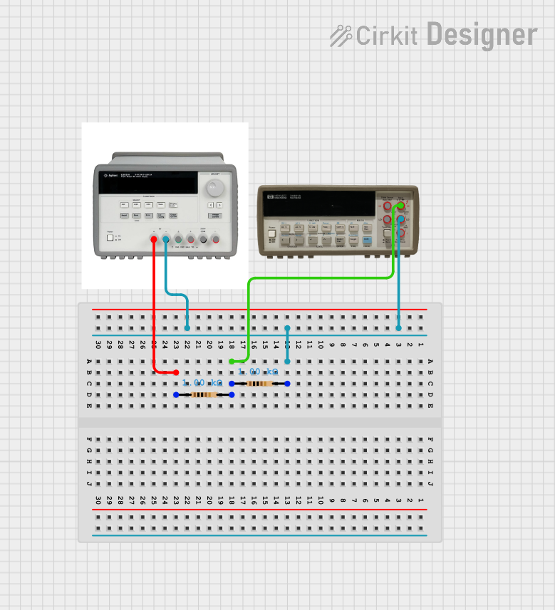 Open Project in Cirkit Designer
Explore Projects Built with Mini Digital Volt/Ammeter
Open Project in Cirkit DesignerOpen Project in Cirkit DesignerOpen Project in Cirkit DesignerOpen Project in Cirkit DesignerCommon Applications and Use Cases
- Monitoring voltage and current in power supply circuits
- Testing batteries and rechargeable cells
- Measuring load current in electronic devices
- Educational projects and prototyping
- Integration into DIY power systems for real-time monitoring
Technical Specifications
Below are the key technical details of the Mini Digital Volt/Ammeter:
| Parameter | Specification |
|---|---|
| Voltage Measurement Range | 0V to 100V DC |
| Current Measurement Range | 0A to 10A DC |
| Operating Voltage | 4.5V to 30V DC |
| Display Type | 3-digit 7-segment LED |
| Accuracy | ±1% (Voltage), ±2% (Current) |
| Refresh Rate | ~500ms |
| Dimensions | ~48mm x 29mm x 21mm |
| Wiring Type | 4-wire or 3-wire configuration |
Pin Configuration and Descriptions
The Mini Digital Volt/Ammeter typically has four wires for connection. Below is the pin configuration:
| Wire Color | Function | Description |
|---|---|---|
| Red | Power Supply Positive (Vcc) | Connect to the positive terminal of the power source. |
| Black | Power Supply Ground (GND) | Connect to the ground terminal of the power source. |
| Yellow | Voltage Measurement Input | Connect to the positive terminal of the voltage to be measured. |
| Blue | Current Measurement Input | Connect in series with the load to measure current. |
Note: Some models may combine the power supply and measurement inputs into a 3-wire configuration. Always refer to the specific datasheet for your model.
Usage Instructions
How to Use the Component in a Circuit
- Determine the Wiring Configuration: Check whether your Mini Digital Volt/Ammeter uses a 4-wire or 3-wire configuration.
- Connect the Power Supply:
- For a 4-wire configuration, connect the red wire to the positive terminal of a 4.5V–30V DC power source and the black wire to the ground.
- For a 3-wire configuration, the power supply and measurement inputs share the same wires.
- Voltage Measurement:
- Connect the yellow wire to the positive terminal of the voltage source you want to measure.
- Ensure the voltage does not exceed the maximum range (100V DC).
- Current Measurement:
- Connect the blue wire in series with the load to measure current.
- Ensure the current does not exceed the maximum range (10A DC).
- Power On the Device: Once all connections are secure, power on the device. The digital display will show the voltage and current readings.
Important Considerations and Best Practices
- Avoid Overloading: Do not exceed the specified voltage (100V DC) or current (10A DC) limits to prevent damage to the device.
- Use Proper Wiring: Ensure all connections are secure and use appropriate wire gauges for current measurement.
- Isolate High Voltages: If measuring high voltages, ensure proper insulation and safety precautions.
- Calibrate if Necessary: Some models may allow calibration for improved accuracy. Refer to the user manual for calibration instructions.
Example: Connecting to an Arduino UNO
The Mini Digital Volt/Ammeter can be used alongside an Arduino UNO to monitor voltage and current in a circuit. Below is an example Arduino sketch to read voltage and current values from the device:
// Example Arduino code to read voltage and current from a Mini Digital Volt/Ammeter
// Note: This code assumes the volt/ammeter is connected to the circuit and powered.

const int voltagePin = A0; // Analog pin connected to the voltage measurement output
const int currentPin = A1; // Analog pin connected to the current measurement output

void setup() {
  Serial.begin(9600); // Initialize serial communication at 9600 baud
  Serial.println("Mini Digital Volt/Ammeter Monitoring");
}

void loop() {
  // Read analog values from the volt/ammeter
  int voltageReading = analogRead(voltagePin);
  int currentReading = analogRead(currentPin);

  // Convert analog readings to actual voltage and current values
  // Assuming a 10-bit ADC (0-1023) and a reference voltage of 5V
  float voltage = (voltageReading / 1023.0) * 100.0; // Scale to 0-100V range
  float current = (currentReading / 1023.0) * 10.0;  // Scale to 0-10A range

  // Print the readings to the Serial Monitor
  Serial.print("Voltage: ");
  Serial.print(voltage);
  Serial.println(" V");

  Serial.print("Current: ");
  Serial.print(current);
  Serial.println(" A");

  delay(1000); // Wait for 1 second before the next reading
}
Note: The above code assumes the Mini Digital Volt/Ammeter outputs analog signals proportional to the measured voltage and current. Verify the output type of your specific model before using this code.
Troubleshooting and FAQs
Common Issues Users Might Face
No Display or Incorrect Readings:
- Cause: Incorrect wiring or insufficient power supply.
- Solution: Double-check all connections and ensure the power supply voltage is within the operating range (4.5V–30V DC).
Flickering or Unstable Readings:
- Cause: Electrical noise or loose connections.
- Solution: Use shorter wires, secure all connections, and add decoupling capacitors if necessary.
Overload Indication:
- Cause: Voltage or current exceeds the specified range.
- Solution: Reduce the input voltage or current to within the device's limits.
Display Not Turning On:
- Cause: Faulty power supply or damaged device.
- Solution: Verify the power supply and check for visible damage. Replace the device if necessary.
FAQs
Q1: Can the Mini Digital Volt/Ammeter measure AC voltage or current?
A1: No, this device is designed for DC voltage and current measurements only.
Q2: Can I use the device without a separate power supply?
A2: Some models support a 3-wire configuration where the measurement inputs share the power supply. Check your model's specifications.
Q3: How do I calibrate the device?
A3: Calibration instructions vary by model. Refer to the user manual or datasheet for detailed steps.
Q4: Is the device waterproof?
A4: No, the Mini Digital Volt/Ammeter is not waterproof. Avoid exposing it to moisture or liquids.
By following this documentation, you can effectively use the Mini Digital Volt/Ammeter for accurate voltage and current measurements in your projects.