Cirkit Designer Logo
Cirkit Designer
Your all-in-one circuit design IDE
Home / 
Component Documentation

How to Use 12V Mini Solenoid Electromagnetic Electric Control Push-Pull: Examples, Pinouts, and Specs

Image of 12V Mini Solenoid Electromagnetic Electric Control Push-Pull
Cirkit Designer LogoDesign with 12V Mini Solenoid Electromagnetic Electric Control Push-Pull in Cirkit Designer

Introduction

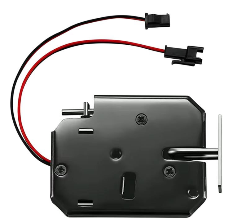
The 12V Mini Solenoid Electromagnetic Electric Control Push-Pull is a compact electromagnetic actuator designed to create linear motion by pushing or pulling an object when energized. It operates on a 12V DC power supply and is widely used in applications requiring precise mechanical movement. This solenoid is ideal for projects involving locking mechanisms, automated systems, robotics, vending machines, and more.

Explore Projects Built with 12V Mini Solenoid Electromagnetic Electric Control Push-Pull

Use Cirkit Designer to design, explore, and prototype these projects online. Some projects support real-time simulation. Click "Open Project" to start designing instantly!
Arduino-Controlled RFM95 Pneumatic Solenoid Valve System
Image of Lorawan valve: A project utilizing 12V Mini Solenoid Electromagnetic Electric Control Push-Pull in a practical application
This circuit controls a 12v pneumatic solenoid valve using an Arduino Pro Mini microcontroller. The Arduino toggles the solenoid valve on and off with a 1-second interval, as programmed in the embedded code. A TIP120 Darlington transistor is used to switch the higher current required by the solenoid, and a 1N4007 diode provides back EMF protection. Additionally, an RFM95 module is interfaced with the Arduino for potential wireless communication capabilities.
Cirkit Designer LogoOpen Project in Cirkit Designer
ESP32-Controlled Water Pump and Solenoid Valve System
Image of fertilizer mixer: A project utilizing 12V Mini Solenoid Electromagnetic Electric Control Push-Pull in a practical application
This circuit is designed to control multiple Mini Diaphragm Water Pumps and a Plastic Solenoid Valve using an ESP32 microcontroller and a 4-channel relay module. The ESP32 is powered by a 12V power supply, and it can switch the relays to turn the pumps and the valve on or off. The power supply also provides 220V AC to 12V DC conversion for the system.
Cirkit Designer LogoOpen Project in Cirkit Designer
ESP32-Based Wi-Fi Controlled Solenoid Valve with Relay
Image of fyp: A project utilizing 12V Mini Solenoid Electromagnetic Electric Control Push-Pull in a practical application
This circuit uses an ESP32 microcontroller to control a 12V relay, which in turn operates a plastic solenoid valve. The ESP32 toggles the relay on and off every second, allowing the solenoid valve to open and close accordingly.
Cirkit Designer LogoOpen Project in Cirkit Designer
ESP32-Controlled Pneumatic Solenoid Valve with MOSFET Switching
Image of ESPooky32: A project utilizing 12V Mini Solenoid Electromagnetic Electric Control Push-Pull in a practical application
This circuit uses an ESP32 microcontroller to control a 12V pneumatic solenoid valve via an IRFZ44N MOSFET as a switch. The ESP32 outputs a control signal through a 220-ohm resistor to the gate of the MOSFET, which in turn controls the power to the solenoid valve from a 12V power supply. A 10k-ohm resistor provides a pull-down for the MOSFET gate to ensure it remains off when not driven by the ESP32.
Cirkit Designer LogoOpen Project in Cirkit Designer

Explore Projects Built with 12V Mini Solenoid Electromagnetic Electric Control Push-Pull

Use Cirkit Designer to design, explore, and prototype these projects online. Some projects support real-time simulation. Click "Open Project" to start designing instantly!
Image of Lorawan valve: A project utilizing 12V Mini Solenoid Electromagnetic Electric Control Push-Pull in a practical application
Arduino-Controlled RFM95 Pneumatic Solenoid Valve System
This circuit controls a 12v pneumatic solenoid valve using an Arduino Pro Mini microcontroller. The Arduino toggles the solenoid valve on and off with a 1-second interval, as programmed in the embedded code. A TIP120 Darlington transistor is used to switch the higher current required by the solenoid, and a 1N4007 diode provides back EMF protection. Additionally, an RFM95 module is interfaced with the Arduino for potential wireless communication capabilities.
Cirkit Designer LogoOpen Project in Cirkit Designer
Image of fertilizer mixer: A project utilizing 12V Mini Solenoid Electromagnetic Electric Control Push-Pull in a practical application
ESP32-Controlled Water Pump and Solenoid Valve System
This circuit is designed to control multiple Mini Diaphragm Water Pumps and a Plastic Solenoid Valve using an ESP32 microcontroller and a 4-channel relay module. The ESP32 is powered by a 12V power supply, and it can switch the relays to turn the pumps and the valve on or off. The power supply also provides 220V AC to 12V DC conversion for the system.
Cirkit Designer LogoOpen Project in Cirkit Designer
Image of fyp: A project utilizing 12V Mini Solenoid Electromagnetic Electric Control Push-Pull in a practical application
ESP32-Based Wi-Fi Controlled Solenoid Valve with Relay
This circuit uses an ESP32 microcontroller to control a 12V relay, which in turn operates a plastic solenoid valve. The ESP32 toggles the relay on and off every second, allowing the solenoid valve to open and close accordingly.
Cirkit Designer LogoOpen Project in Cirkit Designer
Image of ESPooky32: A project utilizing 12V Mini Solenoid Electromagnetic Electric Control Push-Pull in a practical application
ESP32-Controlled Pneumatic Solenoid Valve with MOSFET Switching
This circuit uses an ESP32 microcontroller to control a 12V pneumatic solenoid valve via an IRFZ44N MOSFET as a switch. The ESP32 outputs a control signal through a 220-ohm resistor to the gate of the MOSFET, which in turn controls the power to the solenoid valve from a 12V power supply. A 10k-ohm resistor provides a pull-down for the MOSFET gate to ensure it remains off when not driven by the ESP32.
Cirkit Designer LogoOpen Project in Cirkit Designer

Common Applications and Use Cases

  • Door locking and unlocking mechanisms
  • Automated vending machines
  • Robotics and automation systems
  • Actuation in small mechanical devices
  • DIY electronics projects requiring linear motion

Technical Specifications

Below are the key technical details and pin configuration for the 12V Mini Solenoid:

Key Technical Details

Parameter Value
Operating Voltage 12V DC
Current Consumption ~0.5A (500mA)
Stroke Length 10mm
Force ~300g (at 12V)
Body Material Metal
Coil Resistance ~24Ω
Duty Cycle Intermittent (not for continuous use)
Dimensions ~20mm x 15mm x 30mm
Weight ~50g

Pin Configuration and Descriptions

The solenoid has two wires for connection:

Wire Color Description
Red Positive terminal (+12V DC)
Black Negative terminal (Ground)

Note: Ensure correct polarity when connecting the solenoid to avoid damage.

Usage Instructions

How to Use the Component in a Circuit

  1. Power Supply: Connect the solenoid to a 12V DC power source. Use a power supply capable of providing at least 500mA of current.
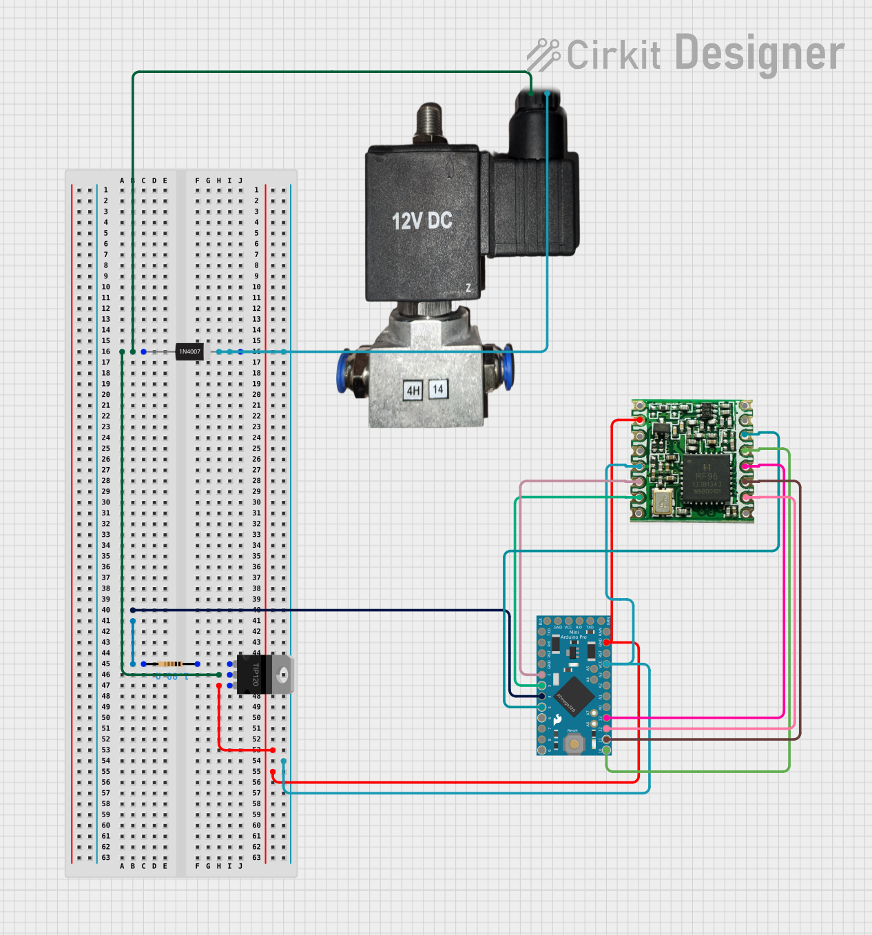
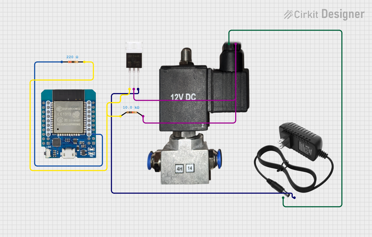
  2. Control Circuit: To control the solenoid, use a transistor or relay module. This allows you to switch the solenoid on and off using a microcontroller or other control logic.
  3. Diode Protection: Always connect a flyback diode (e.g., 1N4007) across the solenoid terminals to protect the circuit from voltage spikes caused by the collapsing magnetic field when the solenoid is turned off.
  4. Microcontroller Integration: If using a microcontroller like an Arduino UNO, connect the solenoid control circuit to a digital output pin via a transistor or relay.

Important Considerations and Best Practices

  • Duty Cycle: Operate the solenoid intermittently to prevent overheating. Continuous operation may damage the coil.
  • Voltage Regulation: Ensure the power supply provides a stable 12V DC to avoid under- or over-voltage conditions.
  • Mounting: Securely mount the solenoid to prevent movement during operation.
  • Polarity: Double-check the polarity of the connections to avoid damage to the solenoid.

Example Arduino Code

Below is an example of how to control the solenoid using an Arduino UNO and a transistor:

// Define the pin connected to the transistor's base
const int solenoidPin = 9;

void setup() {
  pinMode(solenoidPin, OUTPUT); // Set the solenoid pin as an output
}

void loop() {
  digitalWrite(solenoidPin, HIGH); // Energize the solenoid
  delay(1000); // Keep the solenoid active for 1 second
  digitalWrite(solenoidPin, LOW);  // De-energize the solenoid
  delay(1000); // Wait for 1 second before repeating
}

Circuit Notes:

  • Use an NPN transistor (e.g., 2N2222) to control the solenoid. Connect the emitter to ground, the collector to one terminal of the solenoid, and the base to the Arduino pin through a 1kΩ resistor.
  • Connect the other terminal of the solenoid to +12V DC.
  • Place a flyback diode (e.g., 1N4007) across the solenoid terminals, with the cathode connected to the positive terminal.

Troubleshooting and FAQs

Common Issues and Solutions

  1. Solenoid Not Activating:

    • Cause: Insufficient power supply or incorrect wiring.
    • Solution: Verify the power supply provides 12V DC and at least 500mA. Check the wiring for proper connections and polarity.
  2. Overheating:

    • Cause: Continuous operation or excessive duty cycle.
    • Solution: Operate the solenoid intermittently and allow it to cool between activations.
  3. Voltage Spikes Damaging Circuit:

    • Cause: Missing flyback diode.
    • Solution: Install a flyback diode across the solenoid terminals to suppress voltage spikes.
  4. Weak or No Linear Motion:

    • Cause: Insufficient voltage or mechanical obstruction.
    • Solution: Ensure the power supply provides a stable 12V DC. Check for any obstructions in the solenoid's path.

FAQs

Q: Can I use a 9V battery to power the solenoid?
A: No, a 9V battery cannot provide sufficient voltage or current to operate the solenoid effectively. Use a 12V DC power supply.

Q: Can the solenoid be used for continuous operation?
A: No, the solenoid is designed for intermittent use. Continuous operation may cause overheating and damage.

Q: How do I control the solenoid with a microcontroller?
A: Use a transistor or relay module to interface the solenoid with the microcontroller. Refer to the example Arduino code provided above.

Q: What is the purpose of the flyback diode?
A: The flyback diode protects the circuit from voltage spikes generated when the solenoid is turned off, preventing damage to other components.

By following this documentation, you can effectively integrate the 12V Mini Solenoid Electromagnetic Electric Control Push-Pull into your projects and ensure reliable operation.