How to Use RC Front Controller Bottom: Examples, Pinouts, and Specs
Introduction
The RC Front Controller Bottom, manufactured by Home Made, is a vital component in remote-controlled (RC) vehicles. It acts as the primary interface for managing the vehicle's core functions, including steering, acceleration, and braking. This component processes signals received from the remote control and translates them into precise mechanical actions, ensuring smooth and responsive operation.
Explore Projects Built with RC Front Controller Bottom


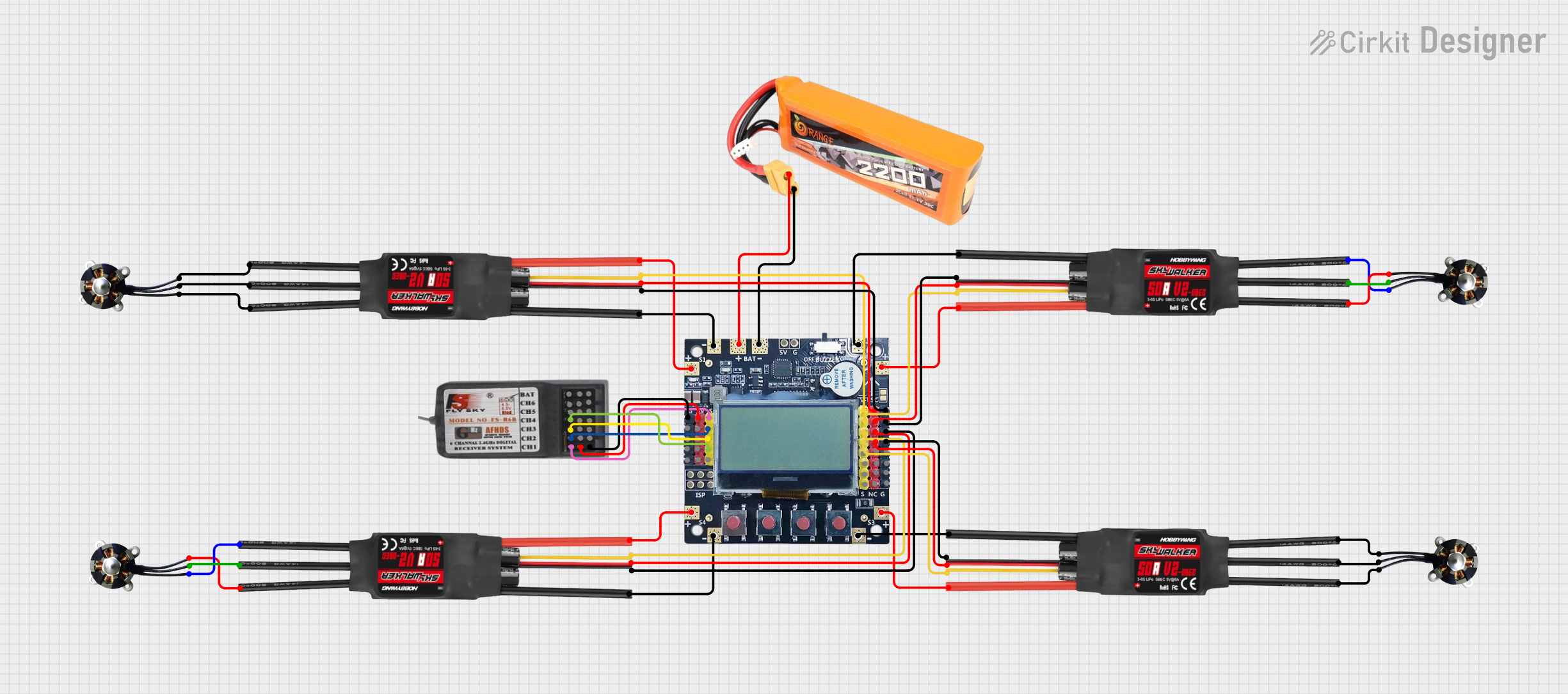

Explore Projects Built with RC Front Controller Bottom
Common Applications and Use Cases
- Remote-controlled cars, trucks, and buggies
- RC boats and other watercraft
- Robotics projects requiring remote control functionality
- Educational and hobbyist RC vehicle kits
Technical Specifications
The RC Front Controller Bottom is designed to handle a wide range of RC vehicle requirements. Below are its key technical details:
General Specifications
| Parameter | Value |
|---|---|
| Operating Voltage | 6V to 12V |
| Maximum Current | 10A |
| Signal Input Type | PWM (Pulse Width Modulation) |
| Operating Temperature | -10°C to 60°C |
| Dimensions | 50mm x 30mm x 15mm |
| Weight | 25g |
Pin Configuration and Descriptions
The RC Front Controller Bottom features a simple pin layout for easy integration into RC systems. Below is the pin configuration:
| Pin Number | Pin Name | Description |
|---|---|---|
| 1 | VCC | Power input (6V to 12V) |
| 2 | GND | Ground connection |
| 3 | PWM_IN | PWM signal input from the remote control receiver |
| 4 | MOTOR_A | Output to motor terminal A |
| 5 | MOTOR_B | Output to motor terminal B |
| 6 | STEERING_OUT | Output signal for steering servo |
Usage Instructions
The RC Front Controller Bottom is straightforward to use in RC vehicle circuits. Follow the steps below to integrate and operate the component effectively:
Step 1: Wiring the Component
- Power Supply: Connect the VCC pin to a 6V-12V power source and the GND pin to the ground.
- Signal Input: Connect the PWM_IN pin to the PWM output of your remote control receiver.
- Motor Connection: Attach the MOTOR_A and MOTOR_B pins to the terminals of the DC motor.
- Steering Servo: Connect the STEERING_OUT pin to the signal input of the steering servo.
Step 2: Configuring the PWM Signal
Ensure that the PWM signal from the remote control receiver matches the expected range of the RC Front Controller Bottom. Typically, the PWM signal should have:
- A frequency of 50Hz
- A duty cycle range of 1ms to 2ms (corresponding to 0% to 100% control)
Step 3: Testing the Setup
- Power on the system and verify that the RC Front Controller Bottom receives the PWM signal.
- Test the motor and steering servo to ensure they respond correctly to remote control inputs.
Important Considerations and Best Practices
- Voltage Compatibility: Ensure the power supply voltage is within the specified range (6V-12V) to avoid damage.
- Heat Management: If the component operates at high currents (close to 10A), consider adding a heat sink or ensuring proper ventilation.
- Signal Integrity: Use shielded cables for the PWM signal to minimize interference.
Example Code for Arduino UNO
If you are using an Arduino UNO to generate the PWM signal for testing or custom control, you can use the following code:
// Example code to generate a PWM signal for the RC Front Controller Bottom
// This code uses pin 9 on the Arduino UNO to output a PWM signal.

const int pwmPin = 9; // Pin connected to the PWM_IN pin of the controller

void setup() {
  pinMode(pwmPin, OUTPUT); // Set the PWM pin as an output
}

void loop() {
  // Generate a PWM signal with a duty cycle of 1.5ms (neutral position)
  analogWrite(pwmPin, 128); // 50% duty cycle (neutral for most RC systems)
  delay(20); // 20ms delay to match 50Hz frequency
}
Troubleshooting and FAQs
Common Issues and Solutions
Motor Does Not Respond
- Cause: No PWM signal or incorrect wiring.
- Solution: Verify the connection between the PWM_IN pin and the remote control receiver. Check the PWM signal using an oscilloscope or logic analyzer.
Steering Servo Not Moving
- Cause: Incorrect connection or incompatible servo.
- Solution: Ensure the STEERING_OUT pin is connected to a compatible servo. Check the servo's operating voltage and signal requirements.
Overheating
- Cause: Excessive current draw or poor ventilation.
- Solution: Reduce the load on the motor or add a heat sink to the controller.
No Power
- Cause: Faulty power supply or loose connections.
- Solution: Check the power supply voltage and ensure all connections are secure.
FAQs
Q: Can I use this controller with a brushless motor?
A: No, the RC Front Controller Bottom is designed for brushed DC motors. For brushless motors, use a compatible electronic speed controller (ESC).
Q: What is the maximum range of the PWM signal?
A: The controller supports a PWM signal range of 1ms to 2ms, corresponding to 0% to 100% control.
Q: Can I use this component with a 3.7V LiPo battery?
A: No, the minimum operating voltage is 6V. Using a 3.7V battery may result in malfunction or damage.
Q: Is this component waterproof?
A: No, the RC Front Controller Bottom is not waterproof. Avoid exposing it to water or moisture.
By following this documentation, you can effectively integrate and operate the RC Front Controller Bottom in your RC vehicle projects.