
How to Use Adafruit ADS7128 8-Channel ADC and GPIO Expander: Examples, Pinouts, and Specs
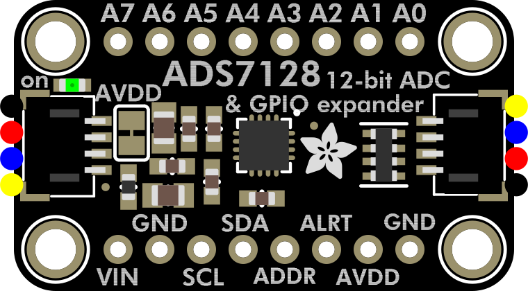
 Design with Adafruit ADS7128 8-Channel ADC and GPIO Expander in Cirkit Designer
Introduction
The Adafruit ADS7128 (Part ID: 6494) is a versatile 8-channel analog-to-digital converter (ADC) with GPIO expansion capabilities. This component is designed to measure multiple analog signals with high precision and provides additional GPIO functionality, making it an excellent choice for interfacing with sensors, actuators, and other devices in embedded systems. Its compact design and I²C interface make it easy to integrate into a wide range of projects.
Explore Projects Built with Adafruit ADS7128 8-Channel ADC and GPIO Expander
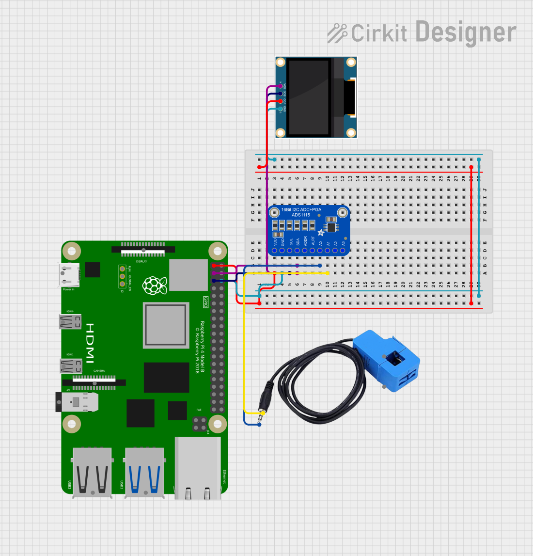 Open Project in Cirkit Designer
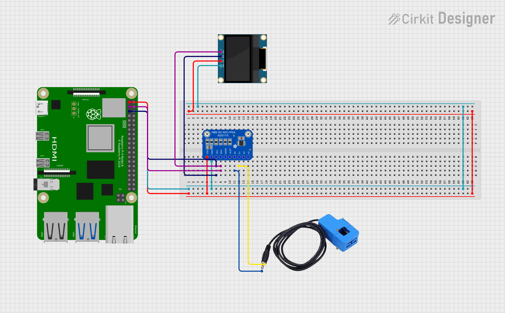 Open Project in Cirkit Designer
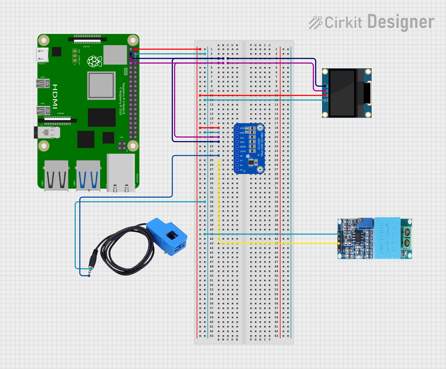 Open Project in Cirkit Designer
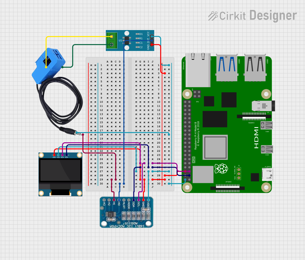 Open Project in Cirkit Designer
Explore Projects Built with Adafruit ADS7128 8-Channel ADC and GPIO Expander
Open Project in Cirkit DesignerOpen Project in Cirkit DesignerOpen Project in Cirkit DesignerOpen Project in Cirkit DesignerCommon Applications and Use Cases
- Monitoring multiple analog sensors (e.g., temperature, light, pressure)
- Expanding GPIO capabilities in microcontroller-based systems
- Data acquisition systems
- Industrial automation and control
- Prototyping and development of IoT devices
Technical Specifications
The Adafruit ADS7128 offers the following key technical features:
| Parameter | Value |
|---|---|
| Supply Voltage (VDD) | 2.7V to 5.5V |
| Analog Input Channels | 8 |
| ADC Resolution | 12-bit |
| Sampling Rate | Up to 188 kSPS |
| Communication Interface | I²C (up to 3.4 MHz) |
| GPIO Pins | 8 (configurable as input or output) |
| Operating Temperature | -40°C to +125°C |
| Package Type | QFN-16 |
Pin Configuration and Descriptions
The ADS7128 has 16 pins, as described in the table below:
| Pin Number | Pin Name | Description |
|---|---|---|
| 1 | VDD | Power supply input (2.7V to 5.5V). |
| 2 | GND | Ground connection. |
| 3 | SDA | I²C data line. |
| 4 | SCL | I²C clock line. |
| 5-12 | AIN0-AIN7 | Analog input channels (can also be configured as GPIO). |
| 13 | ALERT | Interrupt output pin (active low). |
| 14 | ADDR | I²C address selection pin. |
| 15 | RESET | Active-low reset pin. |
| 16 | NC | No connection (leave unconnected). |
Usage Instructions
How to Use the Component in a Circuit
- Power Supply: Connect the VDD pin to a 3.3V or 5V power source and the GND pin to ground.
- I²C Communication: Connect the SDA and SCL pins to the corresponding I²C pins on your microcontroller. Use pull-up resistors (typically 4.7kΩ) on both lines if not already present.
- Analog Inputs: Connect your analog signals to the AIN0-AIN7 pins. Ensure the input voltage does not exceed the supply voltage (VDD).
- GPIO Configuration: If using the pins as GPIO, configure them as input or output via I²C commands.
- Interrupts: Use the ALERT pin to monitor events such as threshold crossings or configuration errors.
- Address Selection: Set the I²C address by connecting the ADDR pin to GND, VDD, or leaving it floating (refer to the datasheet for address mapping).
Important Considerations and Best Practices
- Input Voltage Range: Ensure that the analog input voltage remains within the range of 0V to VDD to avoid damage.
- Bypass Capacitor: Place a 0.1µF ceramic capacitor close to the VDD pin for power supply decoupling.
- I²C Pull-Up Resistors: Verify that pull-up resistors are present on the SDA and SCL lines to ensure proper I²C communication.
- GPIO Current Limit: Do not exceed the maximum current rating for GPIO pins (refer to the datasheet for details).
- Reset Pin: Use the RESET pin to reset the device if needed, or leave it unconnected if not used.
Example Code for Arduino UNO
Below is an example of how to read analog values from the ADS7128 using an Arduino UNO:
#include <Wire.h>

// Define the I²C address of the ADS7128 (default: 0x48)
#define ADS7128_I2C_ADDRESS 0x48

void setup() {
  Wire.begin(); // Initialize I²C communication
  Serial.begin(9600); // Initialize serial communication for debugging

  // Configure the ADS7128 (example: set AIN0 as an analog input)
  Wire.beginTransmission(ADS7128_I2C_ADDRESS);
  Wire.write(0x01); // Write to configuration register
  Wire.write(0x80); // Enable AIN0 as analog input
  Wire.endTransmission();

  Serial.println("ADS7128 initialized.");
}

void loop() {
  // Request a single-ended analog reading from AIN0
  Wire.beginTransmission(ADS7128_I2C_ADDRESS);
  Wire.write(0x10); // Command to read AIN0
  Wire.endTransmission();

  Wire.requestFrom(ADS7128_I2C_ADDRESS, 2); // Request 2 bytes of data
  if (Wire.available() == 2) {
    uint16_t analogValue = Wire.read() << 8 | Wire.read(); // Combine MSB and LSB
    Serial.print("AIN0 Value: ");
    Serial.println(analogValue);
  }

  delay(1000); // Wait 1 second before the next reading
}
Troubleshooting and FAQs
Common Issues and Solutions
No I²C Communication:
- Ensure the SDA and SCL lines are connected correctly.
- Verify that pull-up resistors are present on the I²C lines.
- Check the I²C address and ensure it matches the configuration of the ADDR pin.
Incorrect Analog Readings:
- Confirm that the input voltage is within the range of 0V to VDD.
- Check for noise or interference on the analog input lines.
- Verify the configuration of the input channels via I²C commands.
Device Not Responding:
- Ensure the VDD and GND connections are secure.
- Check the RESET pin and ensure it is not held low.
- Verify the power supply voltage is within the specified range.
FAQs
Q: Can I use the ADS7128 with a 5V microcontroller?
A: Yes, the ADS7128 supports a supply voltage range of 2.7V to 5.5V, making it compatible with both 3.3V and 5V systems.
Q: How do I configure the GPIO pins?
A: The GPIO pins can be configured as input or output via I²C commands. Refer to the datasheet for detailed register settings.
Q: What is the maximum sampling rate of the ADS7128?
A: The ADS7128 supports a maximum sampling rate of 188 kSPS.
Q: Can I use all 8 channels as GPIO?
A: Yes, all 8 channels (AIN0-AIN7) can be configured as GPIO if needed.
Q: Do I need external components to use the ADS7128?
A: You may need pull-up resistors for the I²C lines and a bypass capacitor for the VDD pin. Additional components depend on your specific application.