How to Use logic_level_converter: Examples, Pinouts, and Specs
Introduction
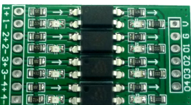
A Logic Level Converter is an essential device used to safely step down or step up voltage levels between different parts of a circuit. This allows components with different voltage requirements to communicate effectively. For instance, it enables a 3.3V microcontroller to interface with a 5V sensor or vice versa. This component is crucial in mixed-voltage systems, ensuring compatibility and protecting sensitive components from damage due to incorrect voltage levels.
Explore Projects Built with logic_level_converter


Explore Projects Built with logic_level_converter
Common Applications and Use Cases
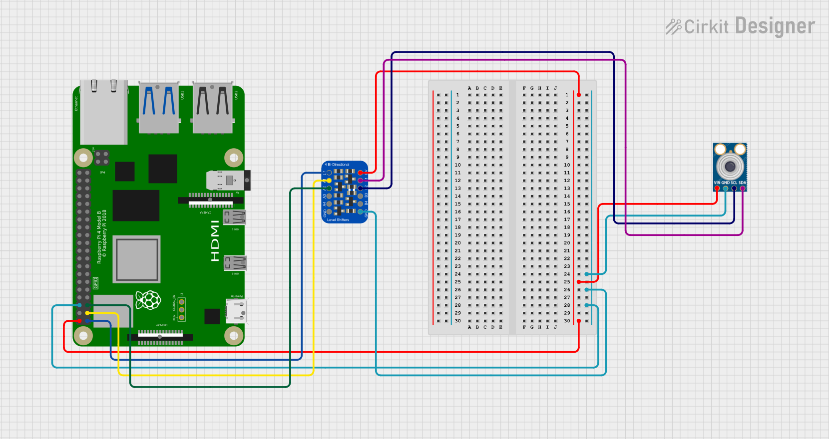
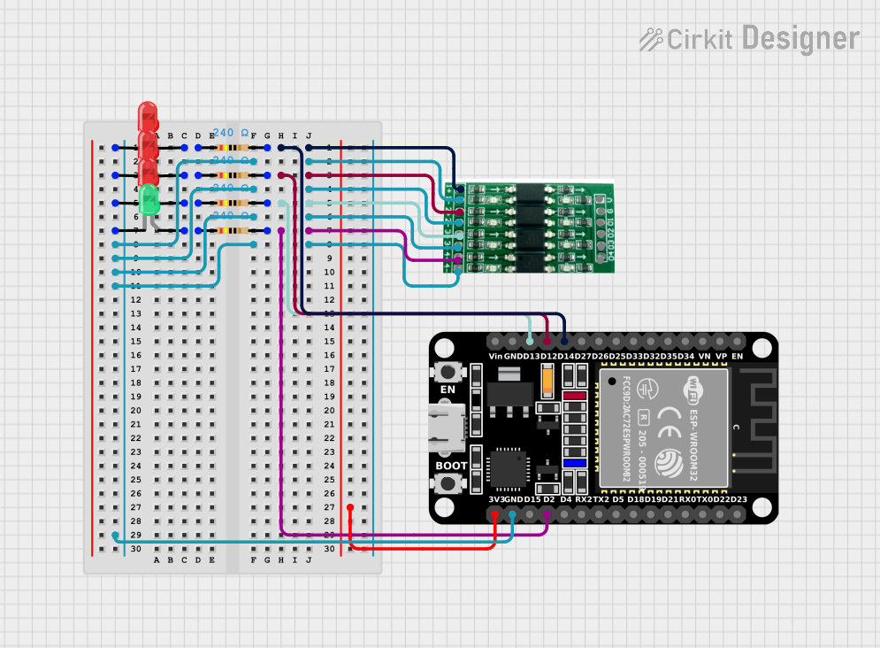
- Microcontroller Interfacing: Connecting 3.3V microcontrollers (e.g., ESP8266, ESP32) with 5V peripherals (e.g., sensors, modules).
- Communication Protocols: Ensuring proper voltage levels for I2C, SPI, UART communication between devices with different voltage requirements.
- Mixed-Voltage Systems: Integrating components with varying voltage levels in a single circuit without risking damage.
Technical Specifications
Key Technical Details
| Parameter | Value |
|---|---|
| Operating Voltage | 1.8V to 5V |
| Maximum Current | 150mA per channel |
| Channels | 4 bi-directional channels |
| Communication | I2C, SPI, UART, GPIO |
| Dimensions | 15mm x 15mm x 3mm |
Pin Configuration and Descriptions
| Pin | Name | Description |
|---|---|---|
| 1 | HV | High Voltage (1.8V to 5V) |
| 2 | LV | Low Voltage (1.8V to 5V) |
| 3 | GND | Ground |
| 4 | TXI | High Voltage Input (TX) |
| 5 | TXO | Low Voltage Output (TX) |
| 6 | RXI | Low Voltage Input (RX) |
| 7 | RXO | High Voltage Output (RX) |
| 8 | CH1 | Channel 1 (Bi-directional) |
| 9 | CH2 | Channel 2 (Bi-directional) |
| 10 | CH3 | Channel 3 (Bi-directional) |
| 11 | CH4 | Channel 4 (Bi-directional) |
Usage Instructions
How to Use the Component in a Circuit
Power Connections:
- Connect the HV pin to the high voltage source (e.g., 5V).
- Connect the LV pin to the low voltage source (e.g., 3.3V).
- Connect the GND pin to the ground of both voltage sources.
Signal Connections:
- For unidirectional communication (e.g., UART):
- Connect the TXI pin to the high voltage signal source.
- Connect the TXO pin to the low voltage signal destination.
- Connect the RXI pin to the low voltage signal source.
- Connect the RXO pin to the high voltage signal destination.
- For bi-directional communication (e.g., I2C):
- Use the CH1 to CH4 pins for the respective channels.
- For unidirectional communication (e.g., UART):
Important Considerations and Best Practices
- Voltage Levels: Ensure that the HV and LV pins are connected to the correct voltage levels to avoid damaging the converter or connected components.
- Current Limitations: Do not exceed the maximum current rating of 150mA per channel.
- Noise Reduction: Use decoupling capacitors close to the power pins to reduce noise and ensure stable operation.
- Proper Grounding: Ensure a common ground between all connected devices to avoid communication issues.
Example: Connecting to an Arduino UNO
To connect a 3.3V sensor to a 5V Arduino UNO using a logic level converter, follow these steps:
Power Connections:
- Connect the HV pin to the 5V pin on the Arduino.
- Connect the LV pin to the 3.3V pin on the Arduino.
- Connect the GND pin to the GND pin on the Arduino.
Signal Connections:
- Connect the sensor's data pin to CH1 on the low voltage side.
- Connect CH1 on the high voltage side to the corresponding Arduino pin (e.g., A0).
Sample Code for Arduino UNO
// Sample code to read data from a 3.3V sensor connected via a logic level converter

const int sensorPin = A0; // Pin connected to CH1 on the high voltage side

void setup() {
  Serial.begin(9600); // Initialize serial communication at 9600 baud
  pinMode(sensorPin, INPUT); // Set the sensor pin as an input
}

void loop() {
  int sensorValue = analogRead(sensorPin); // Read the sensor value
  Serial.println(sensorValue); // Print the sensor value to the serial monitor
  delay(1000); // Wait for 1 second before the next reading
}
Troubleshooting and FAQs
Common Issues Users Might Face
No Communication Between Devices:
- Solution: Check the voltage levels on HV and LV pins. Ensure proper connections and common ground.
Intermittent Data Loss:
- Solution: Use decoupling capacitors close to the power pins. Ensure stable power supply and proper grounding.
Overheating:
- Solution: Ensure the current does not exceed 150mA per channel. Check for short circuits or incorrect connections.
FAQs
Q1: Can I use the logic level converter for both I2C and SPI communication?
- A1: Yes, the logic level converter supports both I2C and SPI communication protocols.
Q2: What happens if I connect the HV and LV pins incorrectly?
- A2: Incorrect connections can damage the logic level converter and connected components. Always double-check the voltage levels before powering the circuit.
Q3: Can I use the logic level converter with a 1.8V device?
- A3: Yes, the logic level converter supports voltage levels as low as 1.8V.
Q4: How many channels can I use simultaneously?
- A4: The logic level converter provides 4 bi-directional channels that can be used simultaneously.
By following this documentation, users can effectively integrate a logic level converter into their circuits, ensuring safe and reliable communication between components with different voltage requirements.