How to Use ESP32-S3-Touch-LCD-3.5B: Examples, Pinouts, and Specs
Introduction
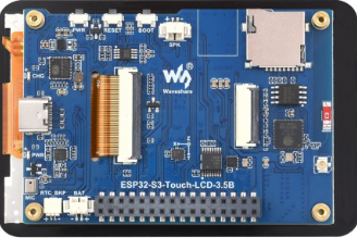
The ESP32-S3-Touch-LCD-3.5B is a versatile 3.5-inch touchscreen display module developed by Waveshare. It is powered by the ESP32-S3 microcontroller, which features dual-core Xtensa LX7 processors, integrated Wi-Fi, and Bluetooth 5.0 connectivity. This module is designed for interactive applications, IoT projects, and smart device interfaces, offering a seamless combination of display and processing capabilities.
Explore Projects Built with ESP32-S3-Touch-LCD-3.5B


Explore Projects Built with ESP32-S3-Touch-LCD-3.5B
Common Applications and Use Cases
- Smart home control panels
- IoT dashboards and monitoring systems
- Industrial automation interfaces
- Educational and prototyping projects
- Portable devices with touch-based user interfaces
Technical Specifications
Key Technical Details
| Parameter | Specification |
|---|---|
| Microcontroller | ESP32-S3 (Xtensa LX7 dual-core, 240 MHz) |
| Display Size | 3.5 inches |
| Display Resolution | 480 x 320 pixels |
| Touchscreen Type | Capacitive |
| Connectivity | Wi-Fi 802.11 b/g/n, Bluetooth 5.0 (LE) |
| Flash Memory | 16 MB |
| PSRAM | 8 MB |
| Operating Voltage | 3.3V |
| Power Supply Input | 5V (via USB-C or external power source) |
| Interface | SPI |
| Dimensions | 85.5 mm x 55.5 mm |
| Weight | 70 g |
Pin Configuration and Descriptions
The ESP32-S3-Touch-LCD-3.5B features a GPIO header for external connections. Below is the pinout description:
| Pin Name | Pin Number | Description |
|---|---|---|
| 3.3V | 1 | 3.3V power output for external components |
| GND | 2 | Ground connection |
| GPIO0 | 3 | General-purpose I/O, can be used for boot mode |
| GPIO2 | 4 | General-purpose I/O, supports ADC and PWM |
| GPIO4 | 5 | General-purpose I/O, supports ADC and PWM |
| GPIO5 | 6 | General-purpose I/O, supports ADC and PWM |
| GPIO18 | 7 | SPI clock (SCK) |
| GPIO19 | 8 | SPI data input (MISO) |
| GPIO23 | 9 | SPI data output (MOSI) |
| GPIO25 | 10 | General-purpose I/O, supports ADC and PWM |
| GPIO26 | 11 | General-purpose I/O, supports ADC and PWM |
| GPIO27 | 12 | General-purpose I/O, supports ADC and PWM |
| EN | 13 | Enable pin for the ESP32-S3 |
Usage Instructions
How to Use the Component in a Circuit
Powering the Module:
- Connect a 5V power source to the USB-C port or use an external 5V supply via the GPIO header.
- Ensure the power supply can provide sufficient current (at least 500 mA).
Connecting to External Devices:
- Use the GPIO pins to interface with sensors, actuators, or other peripherals.
- For SPI communication, connect the SCK, MISO, and MOSI pins to the corresponding pins on the external device.
Programming the ESP32-S3:
- Install the Arduino IDE or ESP-IDF (Espressif IoT Development Framework).
- Select the ESP32-S3 board in the development environment.
- Connect the module to your computer via USB-C and upload your code.
Touchscreen Usage:
- The capacitive touchscreen can be used to detect touch inputs. Libraries such as TFT_eSPI or LVGL (Light and Versatile Graphics Library) can be used to create graphical interfaces.
Important Considerations and Best Practices
- Power Supply: Always use a stable 5V power source to avoid damage to the module.
- GPIO Voltage Levels: The GPIO pins operate at 3.3V logic levels. Avoid connecting 5V signals directly to the GPIO pins.
- Heat Management: If the module is used in high-performance applications, ensure proper ventilation to prevent overheating.
- Firmware Updates: Regularly update the ESP32-S3 firmware to ensure compatibility with the latest libraries and features.
Example Code for Arduino UNO Integration
Below is an example of how to use the ESP32-S3-Touch-LCD-3.5B with the Arduino IDE to display text on the screen:
#include <TFT_eSPI.h> // Include the TFT_eSPI library

TFT_eSPI tft = TFT_eSPI(); // Create an instance of the TFT_eSPI class

void setup() {
  tft.init(); // Initialize the display
  tft.setRotation(1); // Set the display orientation (0-3)
  tft.fillScreen(TFT_BLACK); // Clear the screen with black color

  // Display a message on the screen
  tft.setTextColor(TFT_WHITE, TFT_BLACK); // Set text color and background
  tft.setTextSize(2); // Set text size
  tft.setCursor(10, 10); // Set cursor position
  tft.println("Hello, ESP32-S3!"); // Print text to the screen
}

void loop() {
  // Add your code here for interactive functionality
}
Troubleshooting and FAQs
Common Issues and Solutions
The module does not power on:
- Ensure the USB-C cable is properly connected and the power source is functional.
- Check the power supply voltage and current ratings.
Touchscreen is unresponsive:
- Verify that the touchscreen library is correctly installed and initialized.
- Ensure the SPI connections are secure and configured correctly in the code.
Wi-Fi or Bluetooth is not working:
- Check the firmware version and update if necessary.
- Ensure the correct Wi-Fi credentials are provided in the code.
Display shows incorrect or no output:
- Verify the display initialization code and ensure the correct library is used.
- Check the SPI connections and ensure the pins are correctly assigned in the code.
FAQs
Can I power the module with a battery?
Yes, you can use a 3.7V LiPo battery with a suitable voltage regulator to provide 5V input.What is the maximum touch input resolution?
The touchscreen supports a resolution of 480 x 320 pixels, matching the display resolution.Is the module compatible with other development boards?
Yes, the module can be used with other boards like Raspberry Pi or STM32, provided the SPI interface is configured correctly.Can I use the module outdoors?
The module is not weatherproof. For outdoor use, ensure it is enclosed in a protective case.