
How to Use esp32c6 lcd: Examples, Pinouts, and Specs
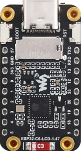
 Design with esp32c6 lcd in Cirkit Designer
Introduction
The ESP32-C6 LCD module by Waveshare is a versatile and powerful microcontroller-based display solution. It combines the capabilities of the ESP32-C6, a Wi-Fi 6 and Bluetooth 5.0-enabled microcontroller, with an integrated LCD interface, making it ideal for IoT applications, smart displays, and user interfaces. The module is designed for low-power, high-performance applications and supports advanced connectivity features.
Explore Projects Built with esp32c6 lcd
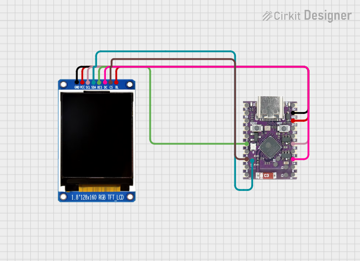 Open Project in Cirkit Designer
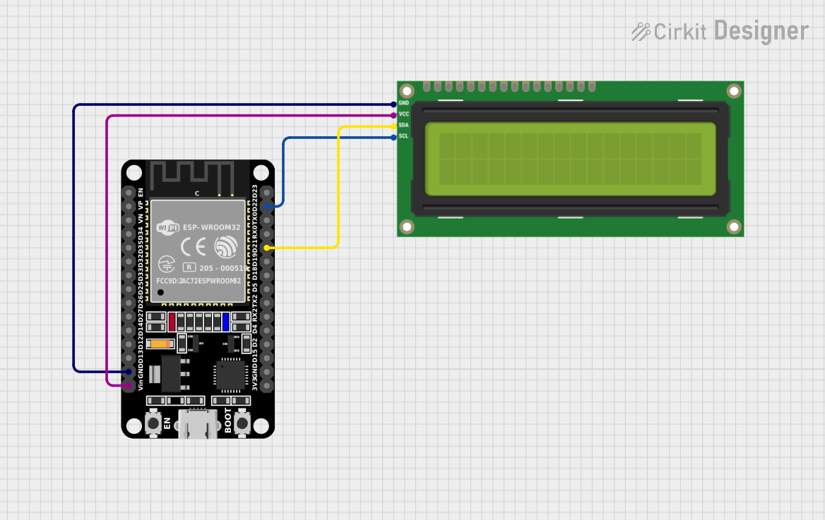 Open Project in Cirkit Designer
 Open Project in Cirkit Designer
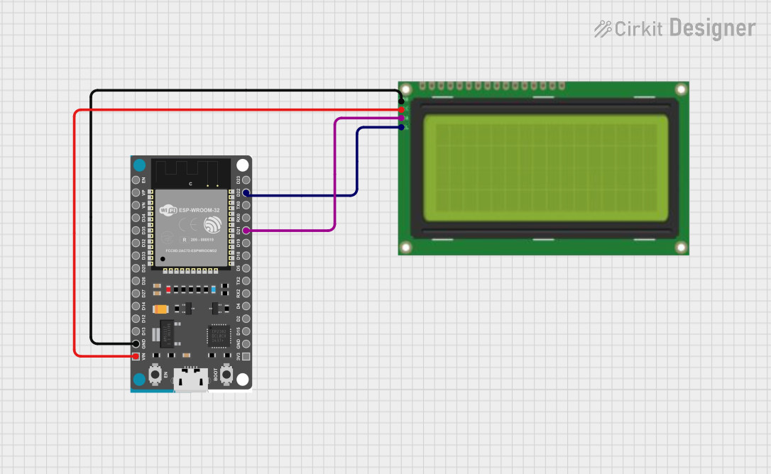 Open Project in Cirkit Designer
Explore Projects Built with esp32c6 lcd
Open Project in Cirkit DesignerOpen Project in Cirkit DesignerOpen Project in Cirkit DesignerOpen Project in Cirkit DesignerCommon Applications and Use Cases
- IoT devices with graphical user interfaces
- Smart home automation systems
- Wearable devices with display functionality
- Industrial control panels
- Educational and prototyping projects
Technical Specifications
Key Technical Details
| Parameter | Specification |
|---|---|
| Microcontroller | ESP32-C6 |
| Wireless Connectivity | Wi-Fi 6, Bluetooth 5.0 |
| LCD Interface | SPI |
| Operating Voltage | 3.3V |
| Power Consumption | Low power (varies by use case) |
| GPIO Pins | Multiple, configurable |
| Flash Memory | 4MB |
| RAM | 512KB |
| Operating Temperature | -40°C to 85°C |
| Dimensions | Varies by specific Waveshare model |
Pin Configuration and Descriptions
| Pin Name | Pin Number | Description |
|---|---|---|
| VCC | 1 | Power supply input (3.3V) |
| GND | 2 | Ground |
| MOSI | 3 | SPI Master Out Slave In (data input) |
| MISO | 4 | SPI Master In Slave Out (data output) |
| SCK | 5 | SPI Clock |
| CS | 6 | Chip Select for LCD |
| RST | 7 | Reset pin for LCD |
| DC | 8 | Data/Command control pin |
| BL | 9 | Backlight control |
| GPIOx | 10+ | General-purpose input/output pins |
Usage Instructions
How to Use the Component in a Circuit
- Power Supply: Connect the VCC pin to a 3.3V power source and GND to ground.
- SPI Communication: Connect the SPI pins (MOSI, MISO, SCK, CS) to the corresponding SPI pins on your microcontroller or development board.
- LCD Control: Use the DC pin to toggle between data and command modes. The RST pin can be used to reset the LCD, and the BL pin controls the backlight.
- GPIO Usage: Configure the GPIO pins as needed for additional functionality, such as buttons or sensors.
Important Considerations and Best Practices
- Ensure the power supply is stable and within the specified voltage range (3.3V).
- Use appropriate pull-up or pull-down resistors for GPIO pins if required.
- Avoid excessive current draw on the backlight pin to prevent damage.
- Use a level shifter if interfacing with a 5V microcontroller to protect the ESP32-C6.
- Follow the SPI timing requirements specified in the ESP32-C6 datasheet for reliable communication.
Example Code for Arduino UNO
Below is an example of how to interface the ESP32-C6 LCD with an Arduino UNO using the SPI protocol. Note that a level shifter is required for voltage compatibility.
#include <SPI.h>

// Pin definitions
#define CS_PIN 10    // Chip Select pin
#define DC_PIN 9     // Data/Command pin
#define RST_PIN 8    // Reset pin
#define BL_PIN 7     // Backlight pin

void setup() {
  // Initialize SPI communication
  SPI.begin();

  // Configure control pins as outputs
  pinMode(CS_PIN, OUTPUT);
  pinMode(DC_PIN, OUTPUT);
  pinMode(RST_PIN, OUTPUT);
  pinMode(BL_PIN, OUTPUT);

  // Reset the LCD
  digitalWrite(RST_PIN, LOW);
  delay(100); // Wait for 100ms
  digitalWrite(RST_PIN, HIGH);

  // Turn on the backlight
  digitalWrite(BL_PIN, HIGH);

  // Initialize the LCD (send initialization commands)
  initializeLCD();
}

void loop() {
  // Example: Display a simple pattern or text
  displayPattern();
}

void initializeLCD() {
  // Send initialization commands to the LCD
  digitalWrite(CS_PIN, LOW);
  digitalWrite(DC_PIN, LOW); // Command mode
  SPI.transfer(0x01); // Example command: Software reset
  digitalWrite(CS_PIN, HIGH);
  delay(120); // Wait for LCD to reset
}

void displayPattern() {
  // Example: Send data to display a pattern
  digitalWrite(CS_PIN, LOW);
  digitalWrite(DC_PIN, HIGH); // Data mode
  for (int i = 0; i < 100; i++) {
    SPI.transfer(0xFF); // Example: Send white pixel data
  }
  digitalWrite(CS_PIN, HIGH);
}
Troubleshooting and FAQs
Common Issues and Solutions
No Display Output:
- Verify the power supply voltage (3.3V) and connections.
- Ensure the SPI pins are correctly connected and configured.
- Check if the backlight (BL) pin is enabled.
Flickering or Unstable Display:
- Ensure proper grounding and minimize noise in the circuit.
- Use decoupling capacitors near the power supply pins.
LCD Not Responding to Commands:
- Confirm the SPI clock speed is within the supported range.
- Check the initialization sequence and ensure commands are sent correctly.
Backlight Not Turning On:
- Verify the BL pin connection and ensure it is set to HIGH.
- Check for excessive current draw or a damaged backlight circuit.
FAQs
Can I use the ESP32-C6 LCD with a 5V microcontroller?
- Yes, but you must use a level shifter to protect the 3.3V logic of the ESP32-C6.
What is the maximum SPI clock speed supported?
- Refer to the ESP32-C6 datasheet for the exact maximum SPI clock speed.
Can I use this module for battery-powered applications?
- Yes, the ESP32-C6 is designed for low-power applications, making it suitable for battery-powered devices.
Is there a library available for easier integration?
- Many open-source libraries, such as Adafruit GFX or TFT_eSPI, support SPI-based LCDs and can be adapted for this module.