Cirkit Designer Logo
Cirkit Designer
Your all-in-one circuit design IDE
Home / 
Component Documentation

How to Use Sim A7670c: Examples, Pinouts, and Specs

Image of Sim A7670c
Cirkit Designer LogoDesign with Sim A7670c in Cirkit Designer

Introduction

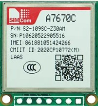
The SIM A7670C is a cellular module designed by Simcom, tailored for IoT (Internet of Things) applications. It supports LTE CAT1 connectivity, providing a balance between speed and power consumption, making it suitable for a wide range of M2M (Machine to Machine) applications. This module is commonly used in applications such as smart metering, wearable devices, environmental monitoring, asset tracking, and remote healthcare.

Explore Projects Built with Sim A7670c

Use Cirkit Designer to design, explore, and prototype these projects online. Some projects support real-time simulation. Click "Open Project" to start designing instantly!
Arduino UNO and SIM A7670c Based SMS Notification System with Battery Power
Image of GSMmodule: A project utilizing Sim A7670c in a practical application
This circuit integrates an Arduino UNO with a Sim A7670c GSM module and a 5V battery to enable SMS communication and control a relay based on input from a switch and a push button. The Arduino handles the logic for sending SMS notifications and toggling the relay, while the GSM module facilitates the SMS functionality.
Cirkit Designer LogoOpen Project in Cirkit Designer
Battery-Powered Emergency Alert System with NUCLEO-F072RB, SIM800L, and GPS NEO 6M
Image of women safety: A project utilizing Sim A7670c in a practical application
This circuit is an emergency alert system that uses a NUCLEO-F072RB microcontroller to send SMS alerts and make calls via a SIM800L GSM module, while obtaining location data from a GPS NEO 6M module. The system is powered by a Li-ion battery and includes a TP4056 module for battery charging and protection, with a rocker switch to control power to the microcontroller.
Cirkit Designer LogoOpen Project in Cirkit Designer
Lilygo 7670e-Based Smart Interface with LCD Display and Keypad
Image of Paower: A project utilizing Sim A7670c in a practical application
This circuit features a Lilygo 7670e microcontroller interfaced with a 16x2 I2C LCD for display, a 4X4 membrane matrix keypad for input, and an arcade button for additional control. It also includes a 4G antenna and a GPS antenna for communication and location tracking capabilities.
Cirkit Designer LogoOpen Project in Cirkit Designer
Arduino Pro Mini Based Temperature Monitoring and GSM Communication System
Image of file alert sms: A project utilizing Sim A7670c in a practical application
This circuit features an Arduino Pro Mini microcontroller connected to a Sim A7670c module for cellular communication, an MLX90614 infrared temperature sensor, and a buzzer for audible alerts. The Arduino facilitates data exchange between the Sim A7670c and the MLX90614 sensor, and controls the buzzer. Power is supplied by a 5V DC source connected to all components, ensuring a common operating voltage.
Cirkit Designer LogoOpen Project in Cirkit Designer

Explore Projects Built with Sim A7670c

Use Cirkit Designer to design, explore, and prototype these projects online. Some projects support real-time simulation. Click "Open Project" to start designing instantly!
Image of GSMmodule: A project utilizing Sim A7670c in a practical application
Arduino UNO and SIM A7670c Based SMS Notification System with Battery Power
This circuit integrates an Arduino UNO with a Sim A7670c GSM module and a 5V battery to enable SMS communication and control a relay based on input from a switch and a push button. The Arduino handles the logic for sending SMS notifications and toggling the relay, while the GSM module facilitates the SMS functionality.
Cirkit Designer LogoOpen Project in Cirkit Designer
Image of women safety: A project utilizing Sim A7670c in a practical application
Battery-Powered Emergency Alert System with NUCLEO-F072RB, SIM800L, and GPS NEO 6M
This circuit is an emergency alert system that uses a NUCLEO-F072RB microcontroller to send SMS alerts and make calls via a SIM800L GSM module, while obtaining location data from a GPS NEO 6M module. The system is powered by a Li-ion battery and includes a TP4056 module for battery charging and protection, with a rocker switch to control power to the microcontroller.
Cirkit Designer LogoOpen Project in Cirkit Designer
Image of Paower: A project utilizing Sim A7670c in a practical application
Lilygo 7670e-Based Smart Interface with LCD Display and Keypad
This circuit features a Lilygo 7670e microcontroller interfaced with a 16x2 I2C LCD for display, a 4X4 membrane matrix keypad for input, and an arcade button for additional control. It also includes a 4G antenna and a GPS antenna for communication and location tracking capabilities.
Cirkit Designer LogoOpen Project in Cirkit Designer
Image of file alert sms: A project utilizing Sim A7670c in a practical application
Arduino Pro Mini Based Temperature Monitoring and GSM Communication System
This circuit features an Arduino Pro Mini microcontroller connected to a Sim A7670c module for cellular communication, an MLX90614 infrared temperature sensor, and a buzzer for audible alerts. The Arduino facilitates data exchange between the Sim A7670c and the MLX90614 sensor, and controls the buzzer. Power is supplied by a 5V DC source connected to all components, ensuring a common operating voltage.
Cirkit Designer LogoOpen Project in Cirkit Designer

Technical Specifications

General Features

  • Frequency Bands:
    • LTE FDD: B1/B2/B3/B4/B5/B7/B8/B12/B13/B18/B19/B20/B25/B26/B28
    • LTE TDD: B39 (for Cat.M1 only)
    • GSM: 850/900/1800/1900 MHz
  • Data Rates:
    • LTE CAT1: Max 10Mbps (DL) / Max 5Mbps (UL)
  • Supply Voltage Range: 3.4V ~ 4.2V, typical 3.8V
  • Operation Temperature: -40°C to +85°C

Interface Features

  • UART Ports: 1
  • SIM Card Interface: 1.8V/3.0V
  • ADC: 1
  • GPIO: Multiple
  • USB 2.0: Full speed

Pin Configuration and Descriptions

Pin Number Name Description
1 VBAT Power supply
2 GND Ground connection
3 RXD UART receive data
4 TXD UART transmit data
5 RST Reset signal
... ... ...

Note: This is a simplified representation of the pin configuration. Refer to the module's datasheet for a complete pinout and description.

Usage Instructions

Integration into a Circuit

  1. Power Supply: Ensure that the power supply is within the specified voltage range and is capable of providing sufficient current for the module's operation.
  2. Antenna: Connect an appropriate LTE antenna to the module to ensure reliable communication.
  3. SIM Card: Insert a Nano SIM card with an active data plan.
  4. Serial Communication: Connect the module's UART pins to a microcontroller or computer to send AT commands and handle data communication.

Best Practices

  • Use a regulated power supply to prevent voltage fluctuations.
  • Place the module away from sources of electromagnetic interference.
  • Implement proper ESD protection when handling the module.
  • Ensure that the antenna is properly tuned for the application's frequency bands.

Troubleshooting and FAQs

Common Issues

  • Power Issues: If the module does not power on, check the power supply and connections.
  • Network Connection: If the module fails to connect to the network, verify the antenna connections and SIM card activation status.
  • Data Communication: If there is no data communication, ensure that the UART connections are correct and the baud rate is properly configured.

FAQs

  • Q: What is the default baud rate for the UART interface?
    • A: The default baud rate is 115200 bps.
  • Q: How do I reset the module?
    • A: The module can be reset by pulling the RST pin low for a short duration.

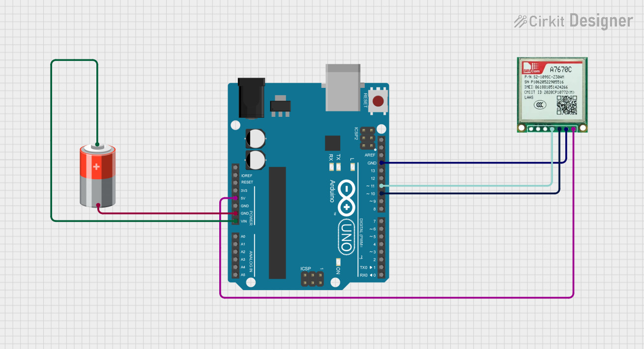
Example Arduino UNO Connection

To connect the SIM A7670C to an Arduino UNO, you can use the following wiring:

  • VBAT to 5V (with a voltage regulator if necessary)
  • GND to GND
  • RXD to pin 3 (SoftwareSerial TX)
  • TXD to pin 2 (SoftwareSerial RX)

Sample Arduino Code

#include <SoftwareSerial.h>

SoftwareSerial simSerial(2, 3); // RX, TX

void setup() {
  // Start the serial communication with the host computer
  Serial.begin(115200);
  while (!Serial) {
    ; // Wait for serial port to connect.
  }

  // Start communication with the SIM A7670C module
  simSerial.begin(115200);
  Serial.println("SIM A7670C module test!");

  // Send AT command to check module status
  simSerial.println("AT");
}

void loop() {
  // Check if the module has responded with "OK"
  if (simSerial.available()) {
    String response = simSerial.readString();
    Serial.print("Module Response: ");
    Serial.println(response);
  }

  // Check if there's any command from the host computer
  if (Serial.available()) {
    String command = Serial.readString();
    simSerial.println(command); // Send the command to the module
  }
}

Note: This code is for testing purposes and assumes that the SIM A7670C module is properly connected and powered. It is important to adjust the baud rate and pins according to your specific setup.

Remember to consult the SIM A7670C datasheet for more detailed information and to ensure proper handling and usage of the module.