How to Use IDC10 SWD: Examples, Pinouts, and Specs
Introduction
The IDC10 SWD (In-Circuit Debugger 10-pin Serial Wire Debug) connector is a compact, standardized interface used for programming and debugging microcontrollers. It is based on the Serial Wire Debug (SWD) protocol, which is a two-wire interface designed for efficient communication with ARM Cortex-M processors. The IDC10 SWD connector is widely used in embedded systems development due to its simplicity and reliability.
Explore Projects Built with IDC10 SWD


Explore Projects Built with IDC10 SWD
Common Applications and Use Cases
- Programming and debugging ARM Cortex-M microcontrollers
- Firmware development and testing
- Integration with development tools such as ST-Link, J-Link, or CMSIS-DAP
- Debugging in low-pin-count or space-constrained designs
Technical Specifications
Key Technical Details
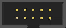
- Connector Type: IDC10 (2x5 pin, 0.1-inch pitch)
- Protocol: Serial Wire Debug (SWD)
- Voltage Levels: Typically 3.3V or 5V (depending on the target microcontroller)
- Pin Count: 10 pins (2 rows of 5)
- Compatibility: ARM Cortex-M microcontrollers and SWD-compatible tools
Pin Configuration and Descriptions
The IDC10 SWD connector uses a 2x5 pin layout. Below is the pinout and description:
| Pin Number | Name | Description |
|---|---|---|
| 1 | VCC | Target voltage reference (3.3V or 5V, depending on the target system) |
| 2 | SWDIO | Serial Wire Debug Input/Output (data line for SWD communication) |
| 3 | GND | Ground connection |
| 4 | SWCLK | Serial Wire Debug Clock (clock line for SWD communication) |
| 5 | GND | Ground connection |
| 6 | NC (No Connect) | Reserved or not connected (varies by implementation) |
| 7 | SWO | Serial Wire Output (optional, used for trace/debug output) |
| 8 | NC (No Connect) | Reserved or not connected (varies by implementation) |
| 9 | RESET | Target microcontroller reset line (optional, used for resetting the MCU) |
| 10 | GND | Ground connection |
Note: Not all pins are required for basic SWD functionality. At a minimum, SWDIO, SWCLK, GND, and VCC are necessary.
Usage Instructions
How to Use the IDC10 SWD in a Circuit
Connect the IDC10 SWD to the Target Microcontroller:
- Ensure the pinout of the connector matches the microcontroller's SWD interface.
- Connect the VCC pin to the target system's voltage reference.
- Connect SWDIO and SWCLK to the corresponding pins on the microcontroller.
- Connect GND to the ground of the target system.
Connect the Debugger/Programmer:
- Use an SWD-compatible debugger (e.g., ST-Link, J-Link) with an IDC10 cable.
- Plug the debugger into the IDC10 SWD connector.
Power the Target System:
- Ensure the target system is powered either through the debugger (if supported) or an external power source.
Program or Debug:
- Use an Integrated Development Environment (IDE) such as Keil, STM32CubeIDE, or IAR Embedded Workbench.
- Configure the IDE to use the connected debugger and SWD protocol.
- Load firmware or debug the application as needed.
Important Considerations and Best Practices
- Voltage Compatibility: Ensure the debugger and target system operate at the same voltage level (e.g., 3.3V or 5V).
- Cable Length: Keep the IDC10 cable as short as possible to minimize signal degradation.
- Pin Alignment: Double-check the pin alignment to avoid damaging the microcontroller or debugger.
- Pull-Up Resistors: Some microcontrollers may require pull-up resistors on the SWDIO or RESET lines for reliable operation.
- SWO Usage: If using the SWO pin for trace output, ensure the debugger and IDE support this feature.
Example: Connecting IDC10 SWD to an Arduino-Compatible Board
While Arduino boards typically do not use SWD, some ARM-based Arduino-compatible boards (e.g., Arduino Due) support SWD for debugging. Below is an example of configuring an SWD connection:
// Example: Configuring SWD pins on an ARM-based Arduino-compatible board
// Note: This is a conceptual example. Actual implementation depends on the board.

void setup() {
  // Configure SWDIO and SWCLK pins as input/output
  pinMode(SWDIO_PIN, INPUT_PULLUP); // SWDIO pin with pull-up resistor
  pinMode(SWCLK_PIN, OUTPUT);       // SWCLK pin as output

  // Initialize debugging interface (if supported by the board)
  Serial.begin(115200); // Optional: Debug output via serial
}

void loop() {
  // Main application code
}
Note: Replace
SWDIO_PINandSWCLK_PINwith the actual pin numbers for your board.
Troubleshooting and FAQs
Common Issues and Solutions
Debugger Not Detecting the Target Microcontroller:
- Cause: Incorrect pin connections or voltage mismatch.
- Solution: Verify the pinout and ensure the debugger and target system share the same voltage level.
Unstable Communication:
- Cause: Long IDC10 cable or noisy environment.
- Solution: Use a shorter cable and ensure proper grounding.
Target Microcontroller Not Resetting:
- Cause: RESET pin not connected or pull-up resistor missing.
- Solution: Connect the RESET pin and add a pull-up resistor if required.
SWO Trace Not Working:
- Cause: Debugger or IDE does not support SWO.
- Solution: Check the debugger and IDE documentation for SWO support and configuration.
FAQs
Q1: Can I use the IDC10 SWD connector with non-ARM microcontrollers?
A1: The IDC10 SWD connector is specifically designed for ARM Cortex-M microcontrollers. For non-ARM microcontrollers, use the appropriate programming/debugging interface.
Q2: What is the maximum cable length for IDC10 SWD?
A2: It is recommended to keep the cable length below 20 cm to ensure reliable communication.
Q3: Do I need all 10 pins for SWD?
A3: No, only SWDIO, SWCLK, GND, and VCC are required for basic SWD functionality. Other pins are optional.
Q4: Can I power the target system through the VCC pin?
A4: Some debuggers support powering the target system through the VCC pin. Check your debugger's specifications to confirm.