How to Use ISD1820: Examples, Pinouts, and Specs
Introduction
The ISD1820 is a versatile voice recording and playback integrated circuit (IC) designed for simple and efficient audio message storage and retrieval. It allows users to record audio messages and play them back with minimal external components. The IC is ideal for applications requiring short audio recordings, such as toys, greeting cards, voice reminders, and other audio playback devices.
Key features of the ISD1820 include:
- On-chip non-volatile memory for audio storage.
- Simple push-button or microcontroller interface for recording and playback.
- Adjustable recording duration (up to 20 seconds, depending on configuration).
- Low power consumption, making it suitable for battery-powered devices.
Explore Projects Built with ISD1820

Explore Projects Built with ISD1820
Technical Specifications
The ISD1820 is designed to operate with minimal external circuitry. Below are its key technical details:
General Specifications
| Parameter | Value |
|---|---|
| Operating Voltage | 2.4V to 5.5V |
| Typical Operating Current | 25mA (during playback) |
| Recording Duration | 8 to 20 seconds (adjustable) |
| Audio Storage | Non-volatile (retains data after power-off) |
| Output Type | Speaker output (8Ω recommended) and AUX output |
| Dimensions | 38mm x 42mm (for module version) |
Pin Configuration and Descriptions
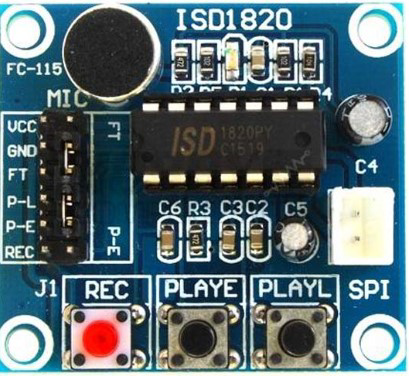
The ISD1820 IC is often used as part of a module. Below is the pinout for the module version:
| Pin Name | Pin Number | Description |
|---|---|---|
| VCC | 1 | Power supply input (2.4V to 5.5V). |
| GND | 2 | Ground connection. |
| REC | 3 | Active-high input for recording. Press or hold to record audio. |
| PLAYE | 4 | Edge-triggered playback. Plays the recorded message once when triggered. |
| PLAYL | 5 | Level-triggered playback. Plays the message as long as the pin is held high. |
| FT | 6 | Feed-through mode. Passes the microphone input directly to the speaker. |
| MIC+ | 7 | Positive terminal for the microphone input. |
| MIC- | 8 | Negative terminal for the microphone input. |
| SP+ | 9 | Positive terminal for the speaker output. |
| SP- | 10 | Negative terminal for the speaker output. |
Usage Instructions
The ISD1820 is straightforward to use and can be operated either manually (via push buttons) or through a microcontroller like an Arduino UNO. Below are the steps to use the ISD1820:
Basic Operation
- Power the Module: Connect the VCC and GND pins to a 3.3V or 5V power source.
- Recording Audio:
- Connect a microphone to the MIC+ and MIC- pins.
- Press and hold the
RECpin (or button) to record audio. Release the pin to stop recording.
- Playing Audio:
- Trigger the
PLAYEpin for edge-triggered playback (plays the message once). - Hold the
PLAYLpin high for level-triggered playback (plays the message continuously).
- Trigger the
- Speaker Connection: Connect an 8Ω speaker to the SP+ and SP- pins for audio output.
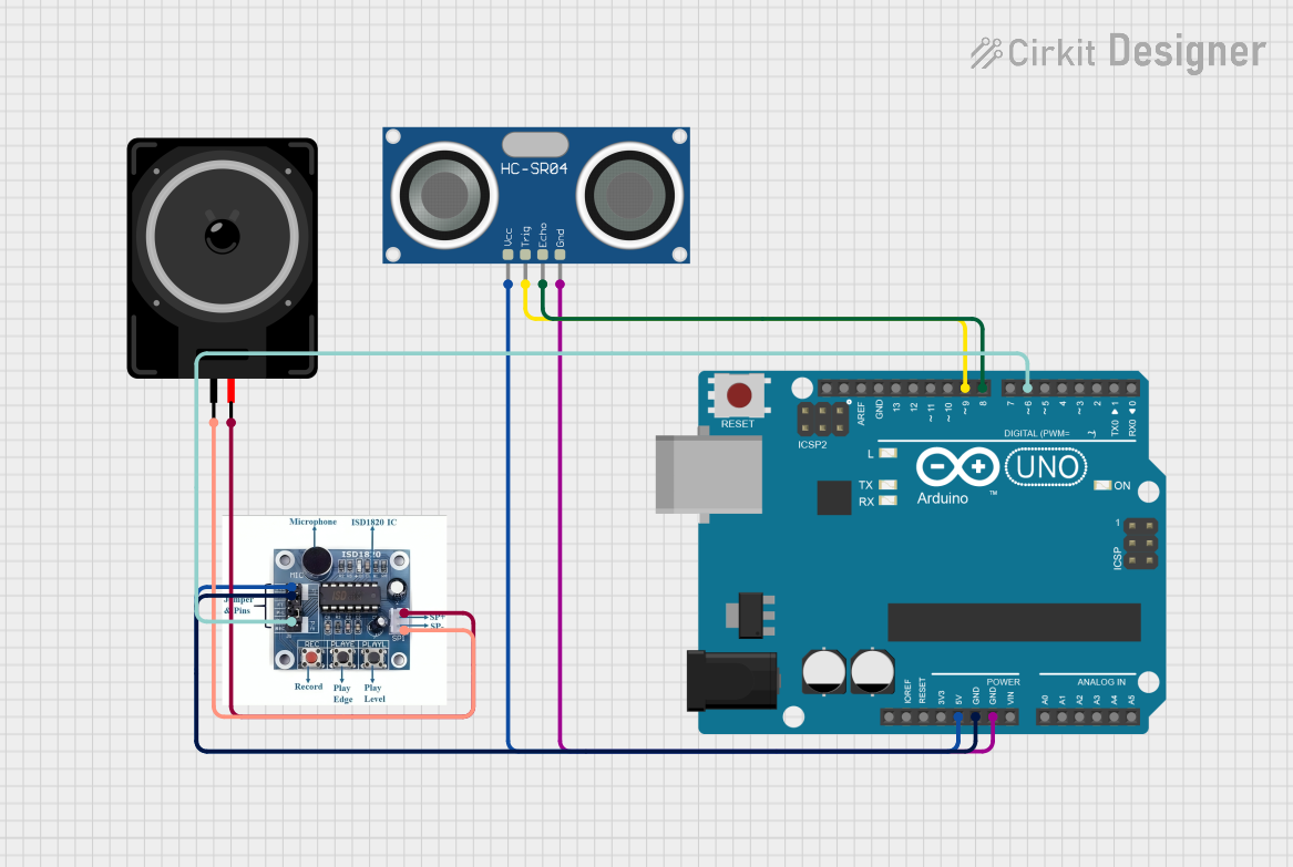
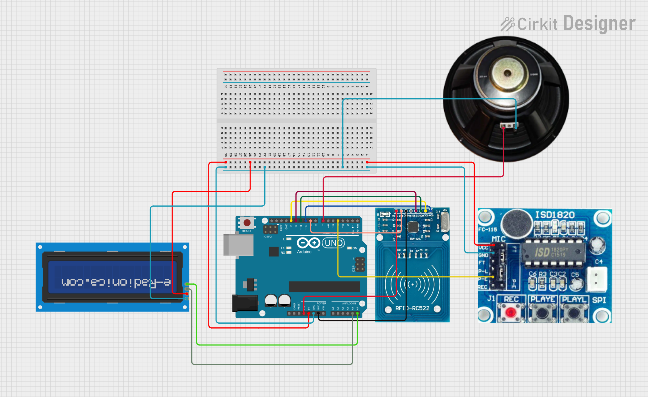
Using with Arduino UNO
The ISD1820 can be controlled via an Arduino UNO for automated recording and playback. Below is an example code snippet:
// ISD1820 Voice Module Control with Arduino UNO
// Connect REC to pin 2, PLAYE to pin 3, and PLAYL to pin 4 on the Arduino.

#define REC_PIN 2    // Pin connected to the REC pin of ISD1820
#define PLAYE_PIN 3  // Pin connected to the PLAYE pin of ISD1820
#define PLAYL_PIN 4  // Pin connected to the PLAYL pin of ISD1820

void setup() {
  pinMode(REC_PIN, OUTPUT);   // Set REC pin as output
  pinMode(PLAYE_PIN, OUTPUT); // Set PLAYE pin as output
  pinMode(PLAYL_PIN, OUTPUT); // Set PLAYL pin as output

  digitalWrite(REC_PIN, LOW);   // Ensure REC is low initially
  digitalWrite(PLAYE_PIN, LOW); // Ensure PLAYE is low initially
  digitalWrite(PLAYL_PIN, LOW); // Ensure PLAYL is low initially
}

void loop() {
  // Example: Record for 5 seconds
  digitalWrite(REC_PIN, HIGH);  // Start recording
  delay(5000);                  // Record for 5 seconds
  digitalWrite(REC_PIN, LOW);   // Stop recording

  delay(2000); // Wait for 2 seconds before playback

  // Example: Play the recorded message once
  digitalWrite(PLAYE_PIN, HIGH); // Trigger playback
  delay(100);                    // Short delay to simulate button press
  digitalWrite(PLAYE_PIN, LOW);  // Stop playback trigger

  delay(5000); // Wait for 5 seconds before repeating
}
Important Considerations
- Power Supply: Ensure a stable power supply to avoid noise or distortion during playback.
- Speaker Impedance: Use an 8Ω speaker for optimal performance.
- Recording Duration: The recording duration depends on the resistor connected to the
ROSCpin (on the IC, not exposed on the module). Adjust this resistor to change the duration (default is ~10 seconds).
Troubleshooting and FAQs
Common Issues
No Sound During Playback:
- Ensure the speaker is properly connected to the SP+ and SP- pins.
- Verify that the recording process was successful (check the REC pin operation).
- Check the power supply voltage (should be between 2.4V and 5.5V).
Distorted Audio:
- Ensure the microphone is properly connected to the MIC+ and MIC- pins.
- Reduce background noise during recording.
- Verify that the speaker impedance is 8Ω.
Playback Not Triggering:
- Check the connections to the PLAYE and PLAYL pins.
- Ensure the control signals are properly sent (e.g., HIGH for playback).
FAQs
Q: Can I extend the recording duration beyond 20 seconds?
A: No, the ISD1820 is limited to a maximum recording duration of 20 seconds. However, you can adjust the duration within this range by modifying the resistor connected to the ROSC pin.
Q: Can I use the ISD1820 with a higher voltage power supply?
A: No, the maximum operating voltage for the ISD1820 is 5.5V. Exceeding this voltage may damage the IC.
Q: Can I connect the ISD1820 to an external amplifier?
A: Yes, you can use the AUX output to connect the ISD1820 to an external amplifier for louder audio playback.
Q: Does the ISD1820 retain the recorded message after power-off?
A: Yes, the ISD1820 uses non-volatile memory to store audio, so the message is retained even when power is removed.