How to Use Fan Controller: Examples, Pinouts, and Specs
Introduction
The Fan Controller is an electronic device designed to regulate the speed and operation of a fan. By adjusting the fan's speed, it enables precise temperature control and enhances energy efficiency. Fan controllers are commonly used in applications such as computer cooling systems, HVAC (Heating, Ventilation, and Air Conditioning) systems, and industrial equipment where maintaining optimal temperatures is critical.
Explore Projects Built with Fan Controller


Explore Projects Built with Fan Controller
Common Applications:
- Computer Systems: To manage CPU, GPU, and case fan speeds for efficient cooling.
- HVAC Systems: For controlling airflow and maintaining desired room temperatures.
- Industrial Equipment: To prevent overheating of machinery and ensure operational safety.
- Home Appliances: For energy-efficient operation of ceiling and exhaust fans.
Technical Specifications
Below are the key technical details of a typical fan controller:
| Parameter | Value |
|---|---|
| Input Voltage Range | 5V to 24V DC |
| Output Voltage Range | 0V to Input Voltage |
| Maximum Output Current | 2A |
| Control Method | PWM (Pulse Width Modulation) |
| Operating Temperature | -20°C to 70°C |
| Dimensions | 50mm x 30mm x 15mm |
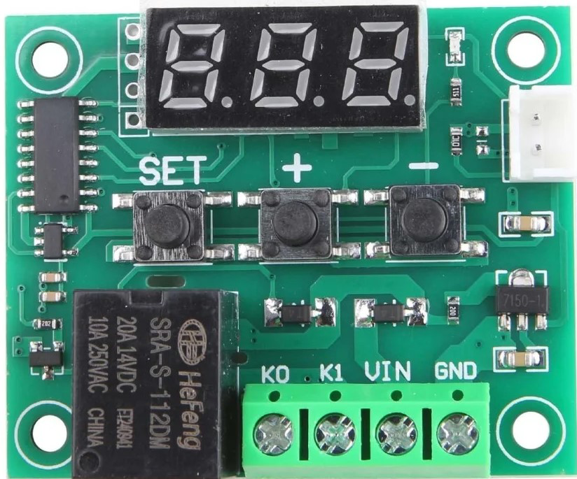
Pin Configuration and Descriptions
The fan controller typically has the following pin configuration:
| Pin | Name | Description |
|---|---|---|
| 1 | VIN | Input voltage pin (connect to power supply, 5V to 24V DC). |
| 2 | GND | Ground pin (connect to the ground of the power supply). |
| 3 | FAN+ | Positive terminal for the fan connection. |
| 4 | FAN- | Negative terminal for the fan connection. |
| 5 | PWM | PWM input pin (connect to a microcontroller or external PWM signal source). |
| 6 | TACH (optional) | Tachometer output pin (provides fan speed feedback, if supported by the fan). |
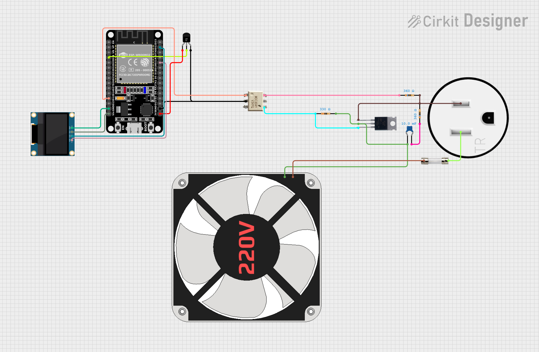
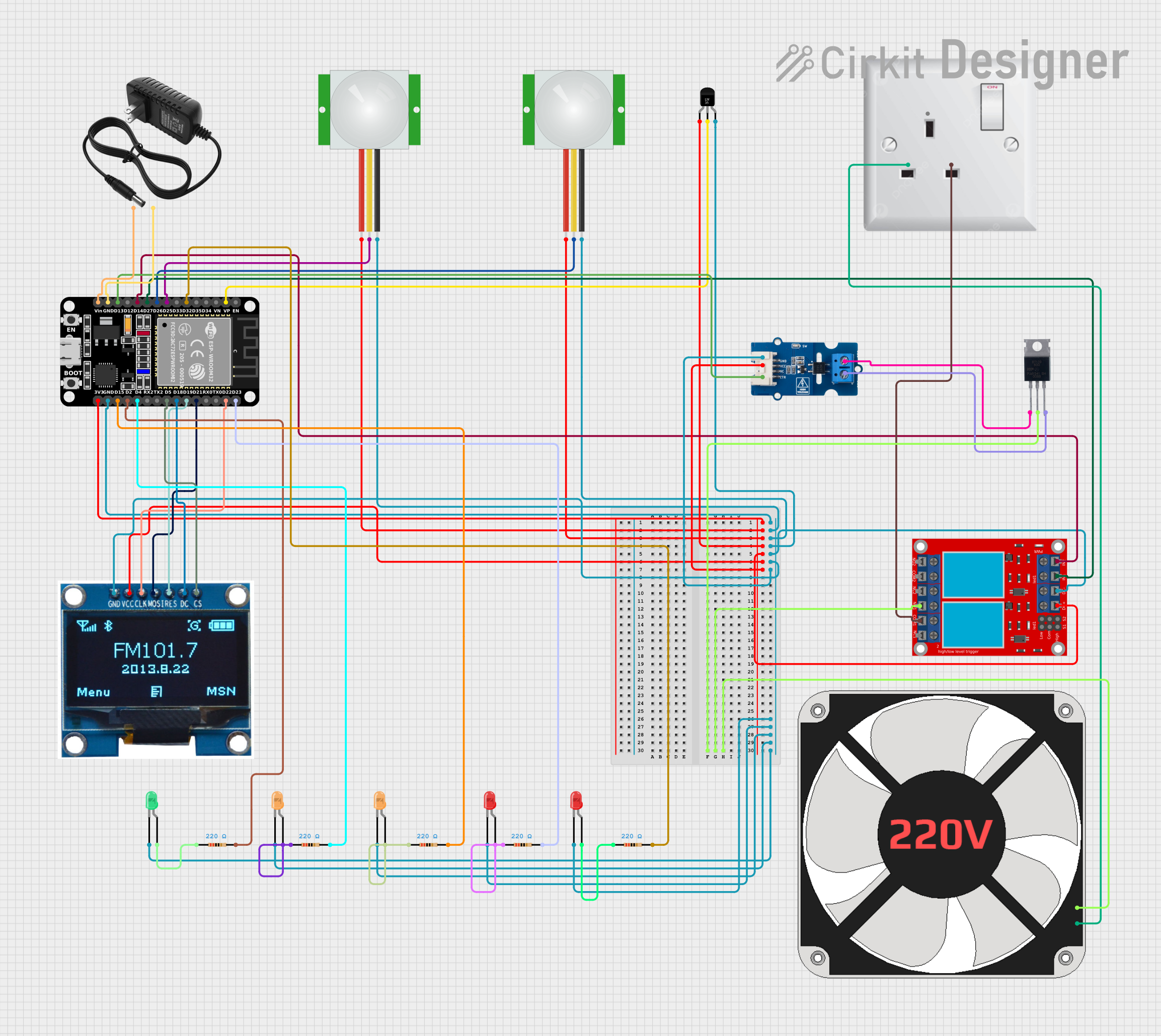
Usage Instructions
How to Use the Fan Controller in a Circuit
- Power Supply: Connect the VIN pin to a DC power supply (5V to 24V) and the GND pin to the ground.
- Fan Connection: Attach the fan's positive wire to the FAN+ pin and the negative wire to the FAN- pin.
- PWM Signal: Provide a PWM signal to the PWM pin from a microcontroller (e.g., Arduino) or an external PWM generator. The duty cycle of the PWM signal determines the fan speed:
- 0% duty cycle: Fan is off.
- 50% duty cycle: Fan runs at half speed.
- 100% duty cycle: Fan runs at full speed.
- Optional Tachometer: If the fan supports speed feedback, connect the TACH pin to a microcontroller's input pin to monitor the fan's RPM.
Important Considerations and Best Practices
- Ensure the input voltage matches the fan's operating voltage to avoid damage.
- Use a heatsink or cooling mechanism if the fan controller operates at high currents for extended periods.
- Verify the PWM frequency requirements of the fan (typically 25kHz for PC fans) and configure the microcontroller accordingly.
- Avoid exceeding the maximum output current (2A) to prevent overheating or damage to the controller.
Example: Using the Fan Controller with an Arduino UNO
Below is an example code to control the fan speed using an Arduino UNO:
// Define the PWM pin connected to the fan controller
const int pwmPin = 9; // Pin 9 supports PWM on Arduino UNO

void setup() {
  pinMode(pwmPin, OUTPUT); // Set the PWM pin as an output
}

void loop() {
  // Gradually increase fan speed from 0% to 100%
  for (int dutyCycle = 0; dutyCycle <= 255; dutyCycle++) {
    analogWrite(pwmPin, dutyCycle); // Write PWM signal to the fan controller
    delay(20); // Wait 20ms before increasing the duty cycle
  }

  // Gradually decrease fan speed from 100% to 0%
  for (int dutyCycle = 255; dutyCycle >= 0; dutyCycle--) {
    analogWrite(pwmPin, dutyCycle); // Write PWM signal to the fan controller
    delay(20); // Wait 20ms before decreasing the duty cycle
  }
}
Troubleshooting and FAQs
Common Issues and Solutions
Fan Does Not Spin:
- Cause: No power supply or incorrect wiring.
- Solution: Verify the power supply voltage and ensure all connections are secure.
Fan Runs at Full Speed Constantly:
- Cause: No PWM signal or incorrect PWM configuration.
- Solution: Check the PWM signal from the microcontroller and ensure the duty cycle is being adjusted correctly.
Fan Speed is Erratic:
- Cause: Incompatible PWM frequency or electrical noise.
- Solution: Confirm the fan's required PWM frequency and adjust the microcontroller settings. Use decoupling capacitors to reduce noise.
Controller Overheats:
- Cause: Excessive current draw or insufficient cooling.
- Solution: Ensure the fan's current does not exceed 2A. Add a heatsink or improve ventilation.
FAQs
Can I use the fan controller with an AC fan? No, this fan controller is designed for DC fans only. For AC fans, use an appropriate AC fan controller.
What PWM frequency should I use? Most DC fans operate with a PWM frequency of 25kHz. Check the fan's datasheet for specific requirements.
Can I control multiple fans with one controller? Yes, but ensure the total current draw of all fans does not exceed the controller's maximum output current (2A).
Is the tachometer pin necessary? No, the tachometer pin is optional and only used if you need to monitor the fan's speed.