
How to Use STM32F103C8T6 Blue Pill: Examples, Pinouts, and Specs
 Design with STM32F103C8T6 Blue Pill in Cirkit Designer
Introduction
The STM32F103C8T6 Blue Pill is a compact and affordable microcontroller development board based on the STM32F103C8T6 chip. It features a 32-bit ARM Cortex-M3 core, 64KB of flash memory, and a wide range of I/O ports, making it ideal for prototyping and embedded applications. Its small form factor and low cost make it a popular choice among hobbyists, students, and professionals for developing IoT devices, robotics, and other embedded systems.
Explore Projects Built with STM32F103C8T6 Blue Pill
 Open Project in Cirkit Designer
 Open Project in Cirkit Designer
 Open Project in Cirkit Designer
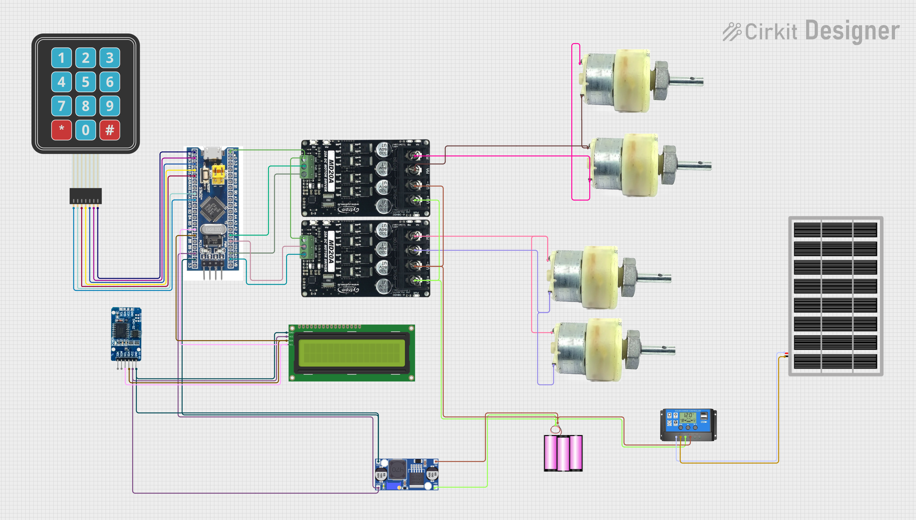 Open Project in Cirkit Designer
Explore Projects Built with STM32F103C8T6 Blue Pill
Open Project in Cirkit DesignerOpen Project in Cirkit DesignerOpen Project in Cirkit DesignerOpen Project in Cirkit DesignerCommon Applications
- IoT devices and smart home automation
- Robotics and motor control
- Data acquisition and sensor interfacing
- Low-power embedded systems
- Educational projects and prototyping
Technical Specifications
Key Technical Details
| Parameter | Specification |
|---|---|
| Microcontroller | STM32F103C8T6 (ARM Cortex-M3) |
| Clock Speed | 72 MHz |
| Flash Memory | 64 KB |
| SRAM | 20 KB |
| Operating Voltage | 3.3V |
| Input Voltage (via USB) | 5V |
| GPIO Pins | 37 |
| Communication Interfaces | UART, SPI, I2C, CAN, USB |
| ADC Resolution | 12-bit (10 channels) |
| PWM Channels | 15 |
| Dimensions | 53 mm x 22 mm |
Pin Configuration and Descriptions
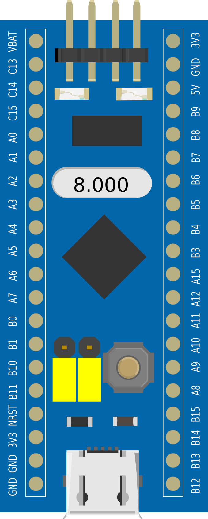
The STM32F103C8T6 Blue Pill has two rows of 20 pins each. Below is a summary of the pin configuration:
| Pin Number | Label | Description |
|---|---|---|
| 1 | GND | Ground |
| 2 | 3.3V | 3.3V Power Output |
| 3 | 5V | 5V Power Input |
| 4-15 | PA0-PA11 | GPIO, ADC, PWM, or Alternate Function |
| 16 | PB0 | GPIO, ADC, or Alternate Function |
| 17-28 | PB1-PB12 | GPIO, ADC, PWM, or Alternate Function |
| 29 | PC13 | GPIO (Low-power pin) |
| 30 | PC14 | GPIO (Low-power pin) |
| 31 | PC15 | GPIO (Low-power pin) |
| 32 | NRST | Reset Pin |
| 33 | BOOT0 | Boot Mode Selection |
| 34-40 | Various | UART, SPI, I2C, CAN, USB, etc. |
Usage Instructions
How to Use the STM32F103C8T6 Blue Pill in a Circuit
Powering the Board:
- The board can be powered via the 5V pin or through the micro-USB port. Ensure the input voltage does not exceed 5V.
- The onboard voltage regulator converts 5V to 3.3V for the microcontroller.
Programming the Board:
- The Blue Pill can be programmed using the Arduino IDE, STM32CubeIDE, or other compatible tools.
- To upload code, connect the board to your computer via a USB-to-Serial adapter or use an ST-Link programmer.
Boot Mode Selection:
- Use the BOOT0 pin to select the boot mode:
- 0: Boot from flash memory (default mode for running user programs).
- 1: Boot from system memory (used for programming via UART).
- Use the BOOT0 pin to select the boot mode:
Connecting Peripherals:
- Use the GPIO pins for interfacing with sensors, actuators, and other devices.
- Configure the pins in software for digital I/O, ADC, PWM, or communication protocols.
Important Considerations
- Voltage Levels: The GPIO pins operate at 3.3V. Avoid connecting 5V signals directly to the pins to prevent damage.
- Pull-Up/Down Resistors: Some pins may require external pull-up or pull-down resistors depending on the application.
- Clock Configuration: Ensure the correct clock settings in your code for optimal performance.
Example Code for Arduino IDE
Below is an example of how to blink an LED connected to pin PA5:
// Define the pin for the LED
#define LED_PIN PA5

void setup() {
  pinMode(LED_PIN, OUTPUT); // Set PA5 as an output pin
}

void loop() {
  digitalWrite(LED_PIN, HIGH); // Turn the LED on
  delay(500);                  // Wait for 500 milliseconds
  digitalWrite(LED_PIN, LOW);  // Turn the LED off
  delay(500);                  // Wait for 500 milliseconds
}
Troubleshooting and FAQs
Common Issues
Board Not Detected by Computer:
- Ensure the correct drivers are installed for the USB-to-Serial adapter or ST-Link programmer.
- Check the USB cable for damage or try a different cable.
Code Upload Fails:
- Verify the BOOT0 pin is set to the correct position for programming.
- Ensure the correct board and port are selected in the Arduino IDE or STM32CubeIDE.
GPIO Pins Not Responding:
- Check the pin configuration in your code.
- Ensure the connected peripherals are functioning correctly and powered properly.
Overheating:
- Verify the input voltage does not exceed 5V.
- Check for short circuits in your circuit connections.
FAQs
Q: Can I use the Blue Pill with 5V sensors?
A: Yes, but you will need a level shifter to safely interface 5V signals with the 3.3V GPIO pins.
Q: How do I reset the board?
A: Press the onboard reset button or momentarily connect the NRST pin to GND.
Q: Can I use the Blue Pill for USB communication?
A: Yes, the STM32F103C8T6 supports USB communication. You can use libraries like USB HID or CDC for implementing USB functionality.
Q: What is the maximum current output of the 3.3V pin?
A: The 3.3V pin can supply up to 100 mA, depending on the input voltage and load.
This concludes the documentation for the STM32F103C8T6 Blue Pill.