Cirkit Designer Logo
Cirkit Designer
Your all-in-one circuit design IDE
Home / 
Component Documentation

How to Use Siemens LOGO! 12/24RC: Examples, Pinouts, and Specs
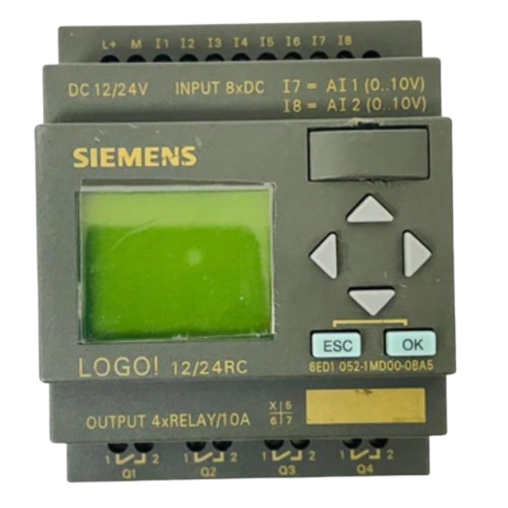

Image of Siemens LOGO! 12/24RC
Cirkit Designer LogoDesign with Siemens LOGO! 12/24RC in Cirkit Designer

Introduction

The Siemens LOGO! 12/24RC (Part ID: 6ED1052-1MD00-0BA6) is a compact and versatile programmable logic controller (PLC) designed for small-scale automation projects. It is part of Siemens' LOGO! series, which is known for its user-friendly interface and robust functionality. This PLC is ideal for applications requiring simple control tasks, such as lighting systems, HVAC control, and small machinery automation.

Explore Projects Built with Siemens LOGO! 12/24RC

Use Cirkit Designer to design, explore, and prototype these projects online. Some projects support real-time simulation. Click "Open Project" to start designing instantly!
Cellular-Enabled IoT Device with Real-Time Clock and Power Management
Image of LRCM PHASE 2 BASIC: A project utilizing Siemens LOGO! 12/24RC in a practical application
This circuit features a LilyGo-SIM7000G module for cellular communication and GPS functionality, interfaced with an RTC DS3231 for real-time clock capabilities. It includes voltage sensing through two voltage sensor modules, and uses an 8-channel opto-coupler for isolating different parts of the circuit. Power management is handled by a buck converter connected to a DC power source and batteries, with a fuse for protection and a rocker switch for on/off control. Additionally, there's an LED for indication purposes.
Cirkit Designer LogoOpen Project in Cirkit Designer
Arduino Mega 2560 Controlled Railway Crossing with Servo Barriers and Audio Alerts
Image of Bahnübergang: A project utilizing Siemens LOGO! 12/24RC in a practical application
This circuit features an Arduino Mega 2560 as the central controller, interfaced with a variety of components including two Servos, a DFPlayer Mini MP3 module with a Loudspeaker for audio output, a Real-Time Clock (RTC DS3231), a 3.5 TFT LCD Shield for display, and multiple pushbuttons with octocouplers for input. The circuit is designed to control a model railway crossing with signal lights (Lichtzeichenanlage), barriers (Servos), and an audio warning system (DFPlayer Mini and Loudspeaker), with the Arduino managing the logic and timing based on button inputs and the RTC. The system uses a 4 x AAA Battery Mount and a separate 3xAA Battery for power, with resistors for current limiting and signal conditioning.
Cirkit Designer LogoOpen Project in Cirkit Designer
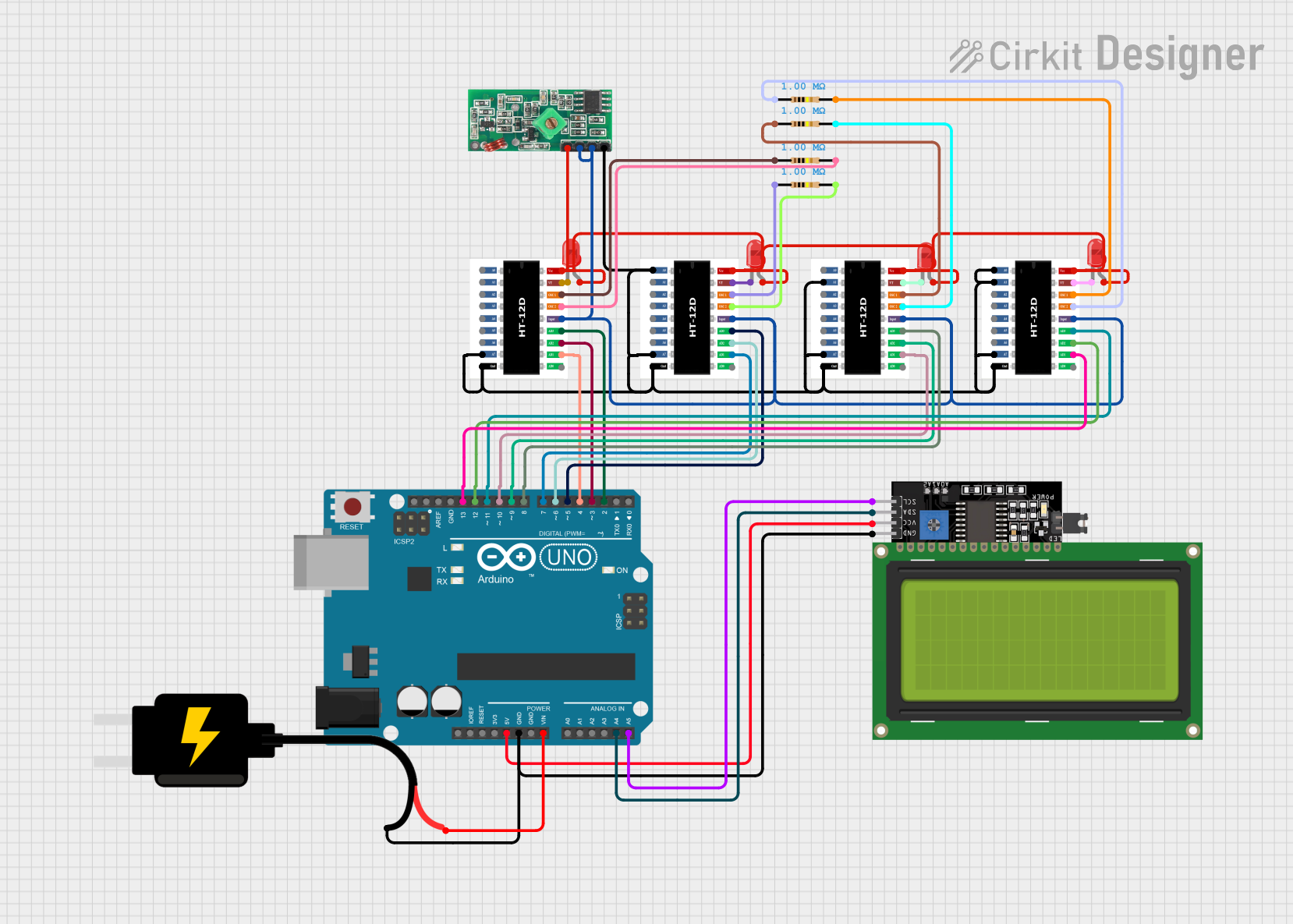
Arduino-Controlled 4-Channel RF Decoder Data Display with I2C LCD Interface
Image of FYP: A project utilizing Siemens LOGO! 12/24RC in a practical application
This circuit comprises an Arduino UNO microcontroller interfaced with four 2-to-12 series CMOS decoders, a 433 MHz RF receiver module, four 1MΩ resistors, four red LEDs, and a 20x4 I2C LCD display. The Arduino reads 3-bit data from each decoder, which are likely receiving signals from the RF receiver, and displays the binary data on the LCD. The LEDs are connected to the decoders' VT (valid transmission) pins, indicating successful data reception, and the entire circuit is powered by a 5V DC source.
Cirkit Designer LogoOpen Project in Cirkit Designer
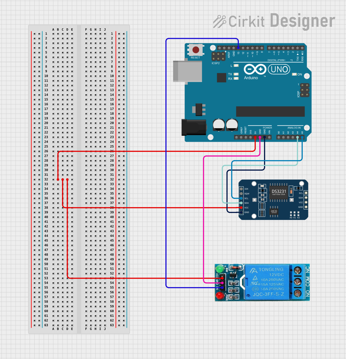
Arduino UNO Controlled Relay with DS3231 RTC
Image of Hooter connections: A project utilizing Siemens LOGO! 12/24RC in a practical application
This circuit features an Arduino UNO microcontroller connected to a DS3231 Real Time Clock (RTC) module and a 12V single-channel relay. The Arduino provides power to both the RTC and the relay, and it communicates with the RTC via I2C using the SDA and SCL lines connected to A4 and A5 respectively. The relay is controlled by the Arduino through a digital output on pin D13, allowing the Arduino to switch external loads on and off based on time events managed by the RTC.
Cirkit Designer LogoOpen Project in Cirkit Designer

Explore Projects Built with Siemens LOGO! 12/24RC

Use Cirkit Designer to design, explore, and prototype these projects online. Some projects support real-time simulation. Click "Open Project" to start designing instantly!
Image of LRCM PHASE 2 BASIC: A project utilizing Siemens LOGO! 12/24RC in a practical application
Cellular-Enabled IoT Device with Real-Time Clock and Power Management
This circuit features a LilyGo-SIM7000G module for cellular communication and GPS functionality, interfaced with an RTC DS3231 for real-time clock capabilities. It includes voltage sensing through two voltage sensor modules, and uses an 8-channel opto-coupler for isolating different parts of the circuit. Power management is handled by a buck converter connected to a DC power source and batteries, with a fuse for protection and a rocker switch for on/off control. Additionally, there's an LED for indication purposes.
Cirkit Designer LogoOpen Project in Cirkit Designer
Image of Bahnübergang: A project utilizing Siemens LOGO! 12/24RC in a practical application
Arduino Mega 2560 Controlled Railway Crossing with Servo Barriers and Audio Alerts
This circuit features an Arduino Mega 2560 as the central controller, interfaced with a variety of components including two Servos, a DFPlayer Mini MP3 module with a Loudspeaker for audio output, a Real-Time Clock (RTC DS3231), a 3.5 TFT LCD Shield for display, and multiple pushbuttons with octocouplers for input. The circuit is designed to control a model railway crossing with signal lights (Lichtzeichenanlage), barriers (Servos), and an audio warning system (DFPlayer Mini and Loudspeaker), with the Arduino managing the logic and timing based on button inputs and the RTC. The system uses a 4 x AAA Battery Mount and a separate 3xAA Battery for power, with resistors for current limiting and signal conditioning.
Cirkit Designer LogoOpen Project in Cirkit Designer
Image of FYP: A project utilizing Siemens LOGO! 12/24RC in a practical application
Arduino-Controlled 4-Channel RF Decoder Data Display with I2C LCD Interface
This circuit comprises an Arduino UNO microcontroller interfaced with four 2-to-12 series CMOS decoders, a 433 MHz RF receiver module, four 1MΩ resistors, four red LEDs, and a 20x4 I2C LCD display. The Arduino reads 3-bit data from each decoder, which are likely receiving signals from the RF receiver, and displays the binary data on the LCD. The LEDs are connected to the decoders' VT (valid transmission) pins, indicating successful data reception, and the entire circuit is powered by a 5V DC source.
Cirkit Designer LogoOpen Project in Cirkit Designer
Image of Hooter connections: A project utilizing Siemens LOGO! 12/24RC in a practical application
Arduino UNO Controlled Relay with DS3231 RTC
This circuit features an Arduino UNO microcontroller connected to a DS3231 Real Time Clock (RTC) module and a 12V single-channel relay. The Arduino provides power to both the RTC and the relay, and it communicates with the RTC via I2C using the SDA and SCL lines connected to A4 and A5 respectively. The relay is controlled by the Arduino through a digital output on pin D13, allowing the Arduino to switch external loads on and off based on time events managed by the RTC.
Cirkit Designer LogoOpen Project in Cirkit Designer

Common Applications and Use Cases

  • Building Automation: Control of lighting, ventilation, and access systems.
  • Industrial Automation: Small machinery control and monitoring.
  • Irrigation Systems: Automated watering schedules for agricultural or landscaping purposes.
  • Energy Management: Load management and energy-saving applications.
  • Custom Projects: Any small-scale automation requiring programmable logic.

Technical Specifications

Key Technical Details

Parameter Value
Manufacturer Siemens
Part ID 6ED1052-1MD00-0BA6
Power Supply Voltage 12/24 V DC
Digital Inputs 12
Relay Outputs 8
Output Type Relay (NO/NC contacts)
Programming Interface LOGO! Soft Comfort software
Display 6-line backlit LCD
Memory 400 function blocks
Clock Integrated real-time clock
Operating Temperature -20°C to +55°C
Mounting DIN rail
Dimensions (W x H x D) 72 mm x 90 mm x 55 mm

Pin Configuration and Descriptions

The LOGO! 12/24RC features a terminal block for connecting inputs, outputs, and power. Below is the pin configuration:

Power Supply and Inputs

Pin Label Description
1 L+ Positive terminal for 12/24 V DC
2 M Negative terminal (ground)
3-14 I1-I12 Digital inputs

Outputs

Pin Label Description
15-22 Q1-Q8 Relay outputs

Usage Instructions

How to Use the Component in a Circuit

  1. Power Connection: Connect a 12/24 V DC power supply to the L+ and M terminals.
  2. Input Connections: Wire your digital input devices (e.g., switches, sensors) to the I1-I12 terminals.
  3. Output Connections: Connect the devices you want to control (e.g., lights, motors) to the Q1-Q8 relay outputs.
  4. Programming: Use Siemens LOGO! Soft Comfort software to create and upload your logic program to the PLC via the programming interface.
  5. Testing: Verify the functionality of your program using the built-in LCD display or the simulation feature in the software.

Important Considerations and Best Practices

  • Power Supply: Ensure the power supply voltage matches the PLC's requirements (12/24 V DC).
  • Input Signal Levels: Verify that input devices provide signals compatible with the PLC's digital inputs.
  • Relay Ratings: Do not exceed the relay output's current and voltage ratings to avoid damage.
  • Programming: Familiarize yourself with the LOGO! Soft Comfort software to efficiently design and debug your logic programs.
  • Environmental Conditions: Install the PLC in an environment within its operating temperature range (-20°C to +55°C) and protect it from excessive dust or moisture.

Example Code for Arduino UNO Integration

Although the LOGO! 12/24RC is a standalone PLC, it can interface with an Arduino UNO for advanced applications. Below is an example of how to send a digital signal from an Arduino to one of the PLC's inputs:

// Example: Sending a HIGH signal from Arduino to LOGO! PLC input
const int plcInputPin = 7; // Arduino pin connected to LOGO! input (e.g., I1)

void setup() {
  pinMode(plcInputPin, OUTPUT); // Set the pin as an output
}

void loop() {
  digitalWrite(plcInputPin, HIGH); // Send HIGH signal to PLC input
  delay(1000); // Wait for 1 second
  digitalWrite(plcInputPin, LOW);  // Send LOW signal to PLC input
  delay(1000); // Wait for 1 second
}

Note: Use a level shifter or resistor divider if the Arduino's 5V output exceeds the PLC's input voltage tolerance.

Troubleshooting and FAQs

Common Issues and Solutions

  1. PLC Does Not Power On

    • Cause: Incorrect power supply voltage or loose connections.
    • Solution: Verify the power supply voltage (12/24 V DC) and check all connections.
  2. Inputs Not Detected

    • Cause: Faulty wiring or incompatible input signal levels.
    • Solution: Check the wiring and ensure the input devices provide signals within the PLC's specifications.
  3. Outputs Not Activating

    • Cause: Exceeding relay output ratings or incorrect wiring.
    • Solution: Verify the load connected to the outputs and ensure it does not exceed the relay's current/voltage ratings.
  4. Program Upload Fails

    • Cause: Communication error between the PLC and the programming device.
    • Solution: Check the programming cable and ensure the LOGO! Soft Comfort software is correctly configured.

FAQs

  • Q: Can the LOGO! 12/24RC be expanded with additional modules?
    A: Yes, the LOGO! 12/24RC supports expansion modules for additional inputs, outputs, and communication capabilities.

  • Q: Is the LOGO! 12/24RC compatible with third-party sensors?
    A: Yes, as long as the sensors provide signals within the PLC's input voltage range.

  • Q: Can I use the LOGO! 12/24RC for time-based automation?
    A: Yes, the integrated real-time clock allows for precise time-based control.

  • Q: What software is required for programming?
    A: Siemens LOGO! Soft Comfort software is used for programming the PLC.

By following this documentation, users can effectively utilize the Siemens LOGO! 12/24RC for their automation projects.