How to Use Wemos D1 R1: Examples, Pinouts, and Specs
Introduction
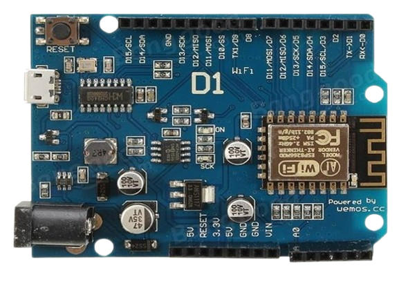
The Wemos D1 R1, manufactured by LOLIN, is a Wi-Fi-enabled microcontroller board based on the ESP8266 chip. It is designed for Internet of Things (IoT) applications, offering seamless integration with Wi-Fi networks. The board features a USB interface for easy programming and a variety of GPIO pins for connecting sensors, actuators, and other peripherals. Its Arduino UNO-like form factor makes it compatible with many Arduino shields, making it a versatile choice for both beginners and experienced developers.
Explore Projects Built with Wemos D1 R1
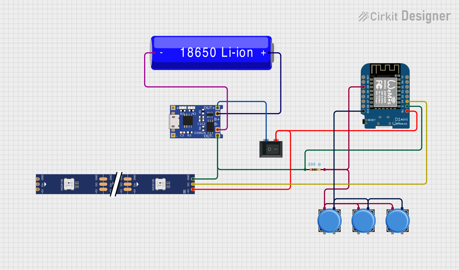

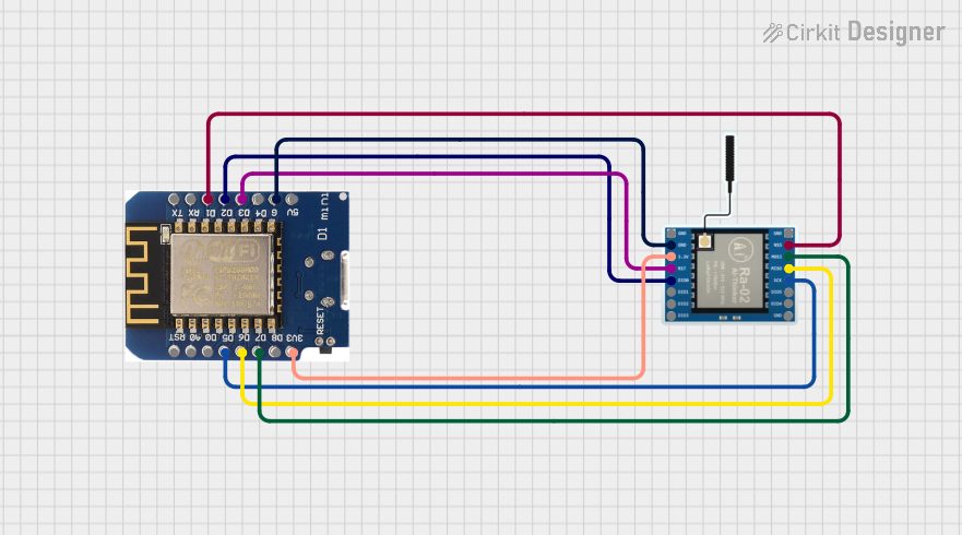

Explore Projects Built with Wemos D1 R1
Common Applications and Use Cases
- Home automation systems
- IoT projects requiring Wi-Fi connectivity
- Remote monitoring and control of devices
- Data logging and cloud integration
- Prototyping with Arduino-compatible shields
Technical Specifications
The Wemos D1 R1 is built around the ESP8266 microcontroller, which provides robust Wi-Fi capabilities and sufficient processing power for a wide range of applications.
Key Technical Details
| Parameter | Specification |
|---|---|
| Microcontroller | ESP8266 |
| Operating Voltage | 3.3V |
| Input Voltage (via USB) | 5V |
| Input Voltage (via VIN) | 7-12V |
| Digital I/O Pins | 11 |
| Analog Input Pins | 1 (10-bit resolution, 0-3.3V range) |
| Clock Speed | 80 MHz (can be overclocked to 160 MHz) |
| Flash Memory | 4 MB |
| Wi-Fi Standard | 802.11 b/g/n |
| USB Interface | Micro-USB |
| Dimensions | 68.6mm x 53.4mm |
Pin Configuration and Descriptions
The Wemos D1 R1 has a pinout similar to the Arduino UNO, but with some differences due to the ESP8266 architecture.
| Pin Name | Description |
|---|---|
| D0-D8 | Digital GPIO pins (can be used for input/output, PWM, I2C, SPI, etc.) |
| A0 | Analog input pin (0-3.3V range, 10-bit resolution) |
| G | Ground pin |
| 3V3 | 3.3V output pin (can power external components) |
| 5V | 5V output pin (powered via USB or VIN) |
| RST | Reset pin (used to reset the microcontroller) |
| TX | UART Transmit pin (used for serial communication) |
| RX | UART Receive pin (used for serial communication) |
| VIN | External power input (7-12V) |
Usage Instructions
The Wemos D1 R1 is easy to use and can be programmed using the Arduino IDE or other compatible development environments. Below are the steps to get started and some best practices for using the board.
How to Use the Component in a Circuit
Powering the Board:
- Connect the board to your computer using a Micro-USB cable for power and programming.
- Alternatively, supply 7-12V to the VIN pin for standalone operation.
Programming the Board:
- Install the Arduino IDE and add the ESP8266 board package via the Boards Manager.
- Select "LOLIN(WEMOS) D1 R1" as the board in the Arduino IDE.
- Write your code and upload it to the board using the Micro-USB connection.
Connecting Peripherals:
- Use the GPIO pins (D0-D8) to connect sensors, actuators, or other devices.
- Use the A0 pin for analog sensors (ensure the input voltage does not exceed 3.3V).
- For Wi-Fi-based projects, use the ESP8266's built-in Wi-Fi library to connect to networks.
Important Considerations and Best Practices
- Voltage Levels: The GPIO pins operate at 3.3V. Avoid applying 5V directly to the pins to prevent damage.
- Analog Input: The A0 pin has a maximum input voltage of 3.3V. Use a voltage divider if your sensor outputs higher voltages.
- Wi-Fi Antenna: Ensure the onboard Wi-Fi antenna is not obstructed for optimal signal strength.
- Power Supply: If powering the board via VIN, ensure the input voltage is within the 7-12V range.
Example Code for Arduino IDE
The following example demonstrates how to connect the Wemos D1 R1 to a Wi-Fi network and print the IP address to the Serial Monitor.
#include <ESP8266WiFi.h> // Include the ESP8266 Wi-Fi library

const char* ssid = "Your_SSID";       // Replace with your Wi-Fi network name
const char* password = "Your_Password"; // Replace with your Wi-Fi password

void setup() {
  Serial.begin(115200); // Initialize serial communication at 115200 baud
  delay(10);

  Serial.println();
  Serial.println("Connecting to Wi-Fi...");

  WiFi.begin(ssid, password); // Start connecting to the Wi-Fi network

  while (WiFi.status() != WL_CONNECTED) {
    delay(500); // Wait for connection
    Serial.print(".");
  }

  Serial.println();
  Serial.println("Wi-Fi connected!");
  Serial.print("IP Address: ");
  Serial.println(WiFi.localIP()); // Print the assigned IP address
}

void loop() {
  // Add your main code here
}
Troubleshooting and FAQs
Common Issues and Solutions
The board is not detected by the Arduino IDE:
- Ensure the correct USB driver is installed for the Wemos D1 R1.
- Check that the correct board and port are selected in the Arduino IDE.
Wi-Fi connection fails:
- Double-check the SSID and password in your code.
- Ensure the Wi-Fi network is within range and not using unsupported security protocols.
GPIO pins not working as expected:
- Verify that the pins are configured correctly in your code (e.g.,
pinMode()function). - Ensure the connected components are compatible with 3.3V logic levels.
- Verify that the pins are configured correctly in your code (e.g.,
Board resets unexpectedly:
- Check the power supply for stability.
- Avoid drawing excessive current from the GPIO pins.
FAQs
Q: Can I use 5V sensors with the Wemos D1 R1?
A: Yes, but you will need a level shifter or voltage divider to step down the 5V signals to 3.3V.
Q: How do I update the firmware on the ESP8266?
A: You can use the ESP8266 Flasher tool or the Arduino IDE to upload new firmware.
Q: Is the Wemos D1 R1 compatible with Arduino shields?
A: Yes, the board has an Arduino UNO-like form factor, but ensure the shield operates at 3.3V logic levels.