How to Use Adafruit I2S Mic SPH0645: Examples, Pinouts, and Specs
Adafruit I2S Microphone SPH0645 Documentation
1. Introduction
The Adafruit I2S Microphone SPH0645 is a compact, high-quality digital microphone that uses the I2S (Inter-IC Sound) interface for transmitting audio data. Unlike traditional analog microphones, this digital microphone eliminates the need for analog-to-digital conversion, providing a cleaner and more accurate audio signal. Its small form factor and low power consumption make it ideal for a wide range of audio capture applications.
Common Applications:
- Voice recognition systems
- Audio recording and streaming
- Sound level monitoring
- IoT devices with audio input
- Smart home assistants and devices
- Environmental sound analysis
2. Technical Specifications
The following table outlines the key technical details of the Adafruit I2S Microphone SPH0645:
| Parameter | Value |
|---|---|
| Operating Voltage | 1.8V to 3.3V |
| Current Consumption | ~1.4 mA |
| Interface | I2S (Inter-IC Sound) |
| Sampling Frequency | 32 kHz to 96 kHz |
| Bit Depth | 24-bit |
| Signal-to-Noise Ratio | 65 dB |
| Sensitivity | -26 dBFS ±3 dB |
| Dimensions | 10.2mm x 10.2mm x 1.3mm |
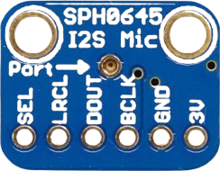
Pin Configuration and Descriptions
The SPH0645 microphone has four pins, as described in the table below:
| Pin Name | Description |
|---|---|
| VIN | Power input (1.8V to 3.3V). Connect to the 3.3V pin of your microcontroller. |
| GND | Ground. Connect to the ground of your circuit. |
| LRCLK | Left/Right clock. Determines whether the microphone outputs left or right data. |
| DOUT | Data output. Outputs the I2S audio data stream. |
3. Usage Instructions
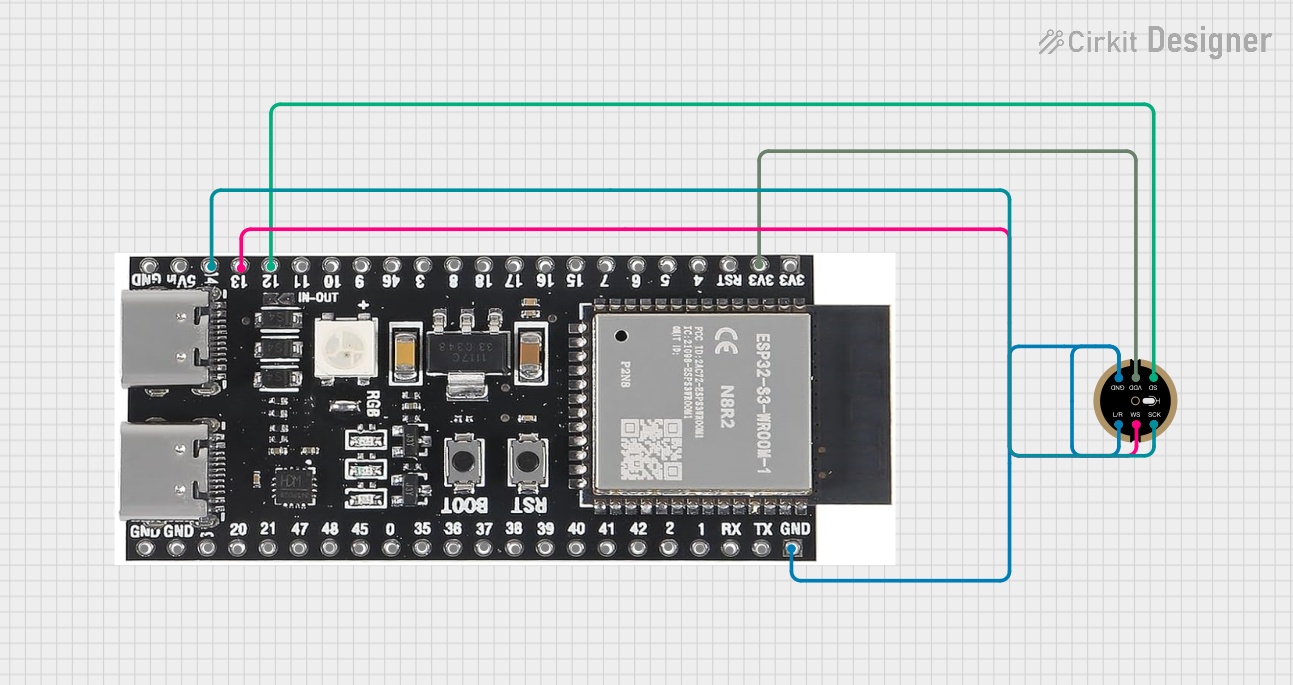
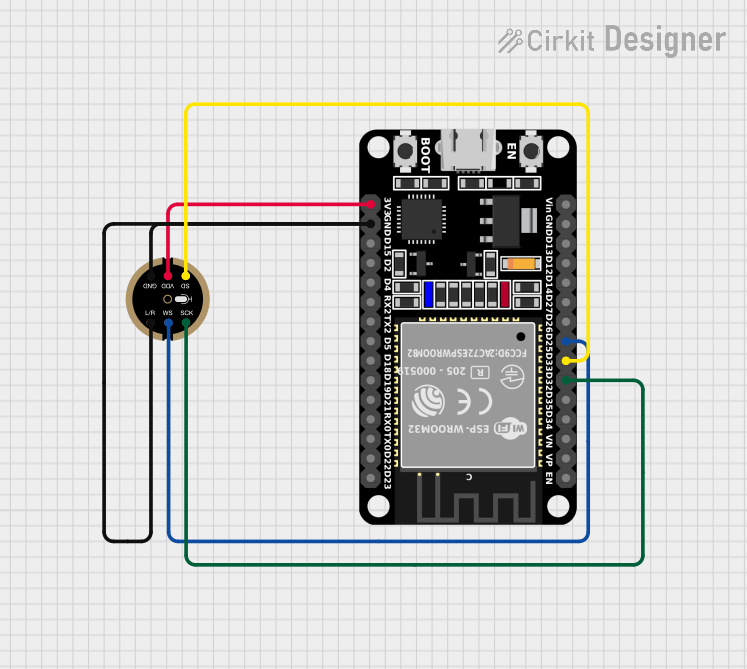
Connecting the SPH0645 to a Microcontroller (e.g., Arduino UNO with I2S Support)
The SPH0645 microphone communicates using the I2S protocol, which requires a microcontroller with I2S support. Below is a step-by-step guide to connect and use the microphone:
Wiring the Microphone:
- Connect the VIN pin of the microphone to the 3.3V pin of your microcontroller.
- Connect the GND pin of the microphone to the GND pin of your microcontroller.
- Connect the LRCLK pin to the LRCLK (or WS) pin of your microcontroller.
- Connect the DOUT pin to the SD (or SDIN) pin of your microcontroller.
Configuring the Microcontroller:
- Ensure your microcontroller supports I2S communication. For example, the Arduino UNO does not natively support I2S, but boards like the ESP32 or Raspberry Pi do.
- Install the necessary I2S library for your microcontroller (e.g.,
I2S.hfor ESP32).
Sample Code for ESP32: Below is an example code snippet to capture audio data from the SPH0645 microphone using an ESP32:
#include <I2S.h> // Include the I2S library for ESP32

// I2S configuration
const int I2S_WS = 25;  // Word Select (LRCLK) pin
const int I2S_SD = 26;  // Serial Data (DOUT) pin
const int I2S_SCK = 27; // Serial Clock (BCLK) pin

void setup() {
  Serial.begin(115200); // Initialize serial communication for debugging

  // Configure I2S with the appropriate pins and settings
  if (!I2S.begin(I2S_PHILIPS_MODE, 16000, 32)) {
    Serial.println("Failed to initialize I2S!");
    while (1); // Halt execution if I2S initialization fails
  }

  I2S.setPins(I2S_SCK, I2S_WS, I2S_SD); // Set I2S pins
  Serial.println("I2S Microphone Initialized!");
}

void loop() {
  int32_t sample = 0; // Variable to store audio sample

  // Read audio data from the microphone
  if (I2S.read(&sample, sizeof(sample)) > 0) {
    Serial.println(sample); // Print the audio sample to the serial monitor
  }
}
Note: Replace the pin numbers with the actual GPIO pins used in your setup.
Important Considerations:
- Power Supply: Ensure the microphone is powered with a stable voltage between 1.8V and 3.3V. Exceeding this range may damage the component.
- I2S Compatibility: Verify that your microcontroller supports I2S communication. The Arduino UNO does not natively support I2S, but boards like the ESP32, STM32, and Raspberry Pi do.
- Clock Configuration: The SPH0645 requires a proper I2S clock signal to function. Ensure your microcontroller is configured to provide the correct clock frequency.
4. Troubleshooting and FAQs
Common Issues and Solutions:
| Issue | Possible Cause | Solution |
|---|---|---|
| No audio data is being received. | Incorrect wiring or pin configuration. | Double-check the wiring and ensure the pins are connected correctly. |
| Distorted or noisy audio output. | Incorrect I2S clock frequency. | Verify that the I2S clock is set to a supported frequency (e.g., 32 kHz). |
| Microphone not powering on. | Insufficient or unstable power supply. | Ensure the VIN pin is connected to a stable 3.3V power source. |
| Audio data is not synchronized. | LRCLK pin not properly configured. | Ensure the LRCLK pin is connected and configured correctly in the code. |
Frequently Asked Questions:
Can I use the SPH0645 with an Arduino UNO?
- The Arduino UNO does not natively support I2S communication. Consider using an ESP32, STM32, or Raspberry Pi for this microphone.
What is the maximum sampling rate supported by the SPH0645?
- The SPH0645 supports sampling rates up to 96 kHz.
Can I use multiple SPH0645 microphones in a single project?
- Yes, you can use multiple microphones by configuring the LRCLK pin to differentiate between left and right channels.
How do I process the audio data from the microphone?
- The raw audio data can be processed using digital signal processing (DSP) techniques or libraries, depending on your application.
5. Additional Resources
This documentation provides a comprehensive guide to using the Adafruit I2S Microphone SPH0645. Whether you're a beginner or an experienced user, this guide will help you integrate the microphone into your projects with ease.
Explore Projects Built with Adafruit I2S Mic SPH0645
Explore Projects Built with Adafruit I2S Mic SPH0645