How to Use hi-link: Examples, Pinouts, and Specs
Introduction
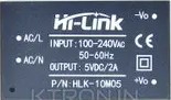
The Hi-Link is a compact and efficient DC-DC converter module designed to step up or step down voltage levels in electronic circuits. It is widely used in applications requiring reliable voltage regulation, such as powering microcontrollers, sensors, and other low-power devices. Its high efficiency and small form factor make it an ideal choice for embedded systems, IoT devices, and industrial automation.
Explore Projects Built with hi-link

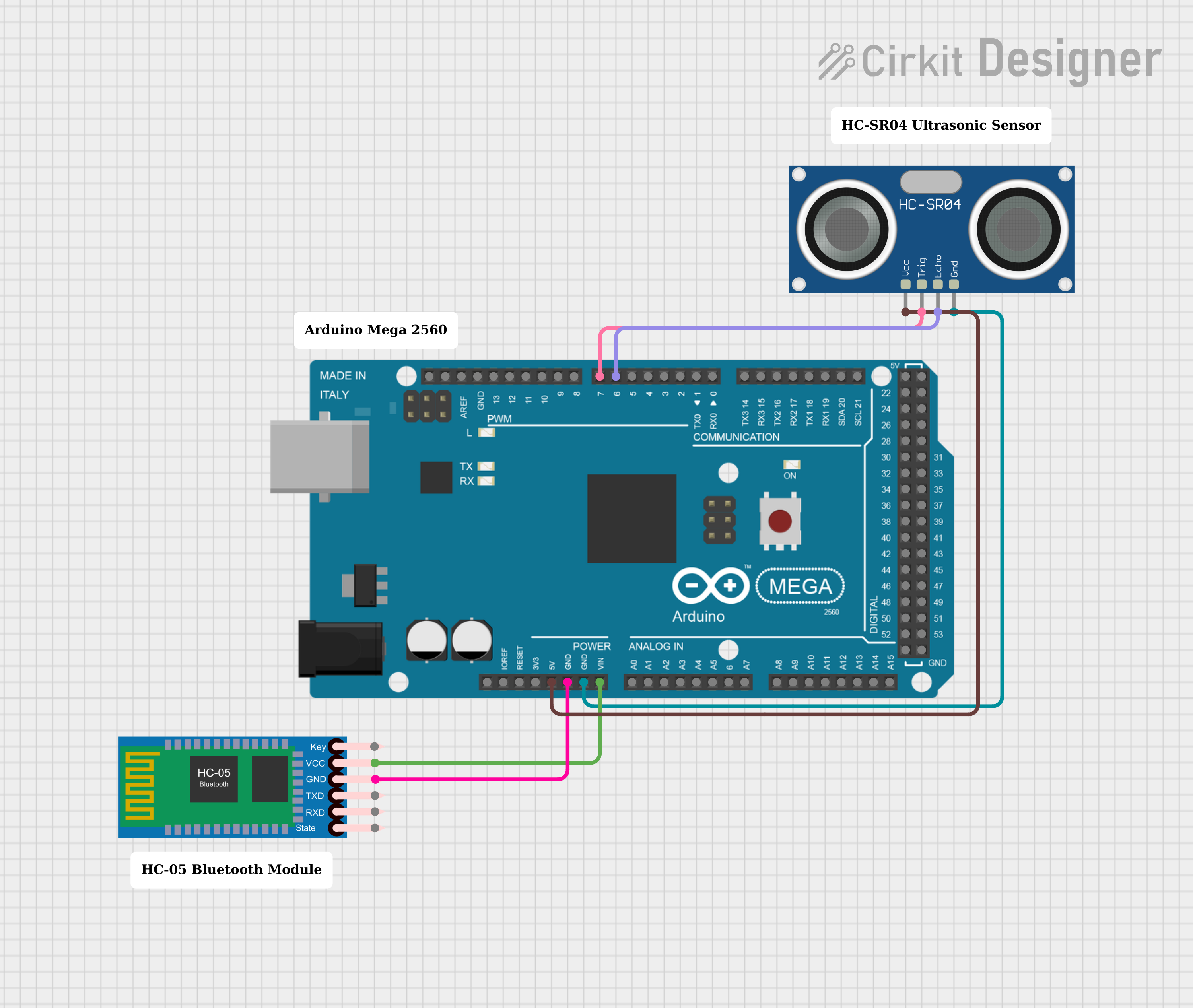
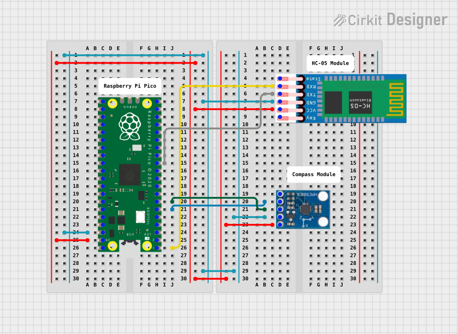
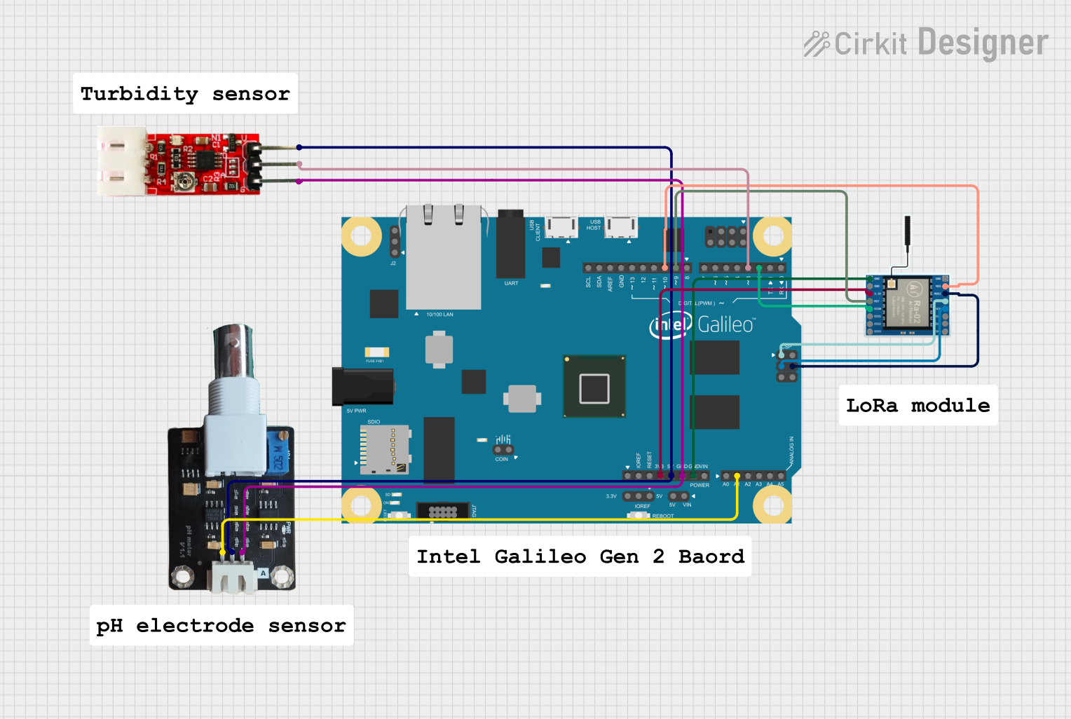
Explore Projects Built with hi-link
Common Applications and Use Cases
- Powering microcontrollers (e.g., Arduino, ESP32, Raspberry Pi)
- Voltage regulation in IoT devices
- Industrial automation systems
- Battery-powered devices
- LED drivers and lighting systems
Technical Specifications
Below are the key technical details for a typical Hi-Link DC-DC converter module. Note that specifications may vary depending on the specific model.
General Specifications
| Parameter | Value |
|---|---|
| Input Voltage Range | 4.5V to 28V |
| Output Voltage Options | 3.3V, 5V, 12V, 24V (model-dependent) |
| Output Current | Up to 2A (model-dependent) |
| Efficiency | Up to 90% |
| Operating Temperature | -40°C to +85°C |
| Dimensions | Compact (e.g., 25mm x 25mm x 15mm) |
Pin Configuration and Descriptions
| Pin Number | Pin Name | Description |
|---|---|---|
| 1 | VIN | Input voltage (connect to power source) |
| 2 | GND | Ground (common ground for input and output) |
| 3 | VOUT | Regulated output voltage |
Usage Instructions
How to Use the Hi-Link in a Circuit
Connect the Input Voltage (VIN):
- Ensure the input voltage is within the specified range for your Hi-Link model.
- Connect the positive terminal of your power source to the VIN pin.
Connect the Ground (GND):
- Connect the ground of your power source and the circuit to the GND pin.
Connect the Output Voltage (VOUT):
- The VOUT pin provides the regulated output voltage.
- Connect this pin to the load or device you want to power.
Add Decoupling Capacitors (Optional):
- For improved stability, place a capacitor (e.g., 10µF) across the VOUT and GND pins.
Important Considerations and Best Practices
- Input Voltage Range: Always ensure the input voltage is within the specified range to avoid damaging the module.
- Heat Dissipation: If the module operates at high currents, ensure proper ventilation or heat sinking to prevent overheating.
- Polarity Protection: Double-check the polarity of the input connections to avoid damage.
- Load Requirements: Ensure the load does not exceed the maximum output current rating of the module.
Example: Using Hi-Link with Arduino UNO
Below is an example of how to use a Hi-Link module to power an Arduino UNO with a 5V output.
Circuit Connections
- Connect a 12V DC power source to the VIN and GND pins of the Hi-Link module.
- Connect the VOUT pin of the Hi-Link module to the 5V pin of the Arduino UNO.
- Connect the GND pin of the Hi-Link module to the GND pin of the Arduino UNO.
Sample Code
// Example code for Arduino UNO powered by a Hi-Link module
// This code blinks an LED connected to pin 13

void setup() {
  pinMode(13, OUTPUT); // Set pin 13 as an output
}

void loop() {
  digitalWrite(13, HIGH); // Turn the LED on
  delay(1000);            // Wait for 1 second
  digitalWrite(13, LOW);  // Turn the LED off
  delay(1000);            // Wait for 1 second
}
Troubleshooting and FAQs
Common Issues and Solutions
No Output Voltage:
- Cause: Input voltage is outside the specified range.
- Solution: Verify the input voltage and ensure it matches the module's requirements.
Overheating:
- Cause: Excessive load current or poor ventilation.
- Solution: Reduce the load or improve heat dissipation with a heatsink or fan.
Output Voltage Fluctuations:
- Cause: Insufficient decoupling or unstable input voltage.
- Solution: Add decoupling capacitors (e.g., 10µF and 0.1µF) across the VOUT and GND pins.
Module Not Working After Connection:
- Cause: Incorrect polarity or short circuit.
- Solution: Double-check all connections and ensure correct polarity.
FAQs
Q: Can I use the Hi-Link module to power a Raspberry Pi?
A: Yes, but ensure the output voltage and current rating of the Hi-Link module meet the Raspberry Pi's power requirements.
Q: Is the Hi-Link module safe for long-term use?
A: Yes, the Hi-Link module is designed for reliable operation. However, ensure proper heat dissipation and avoid exceeding its specifications.
Q: Can I use the Hi-Link module with a battery?
A: Yes, as long as the battery voltage is within the input range of the module.
Q: Do I need additional components to use the Hi-Link module?
A: While not strictly necessary, adding decoupling capacitors can improve stability and performance.
This concludes the documentation for the Hi-Link DC-DC converter module.