Cirkit Designer Logo
Cirkit Designer
Your all-in-one circuit design IDE
Home / 
Component Documentation

How to Use ESP32: Examples, Pinouts, and Specs

Image of ESP32
Cirkit Designer LogoDesign with ESP32 in Cirkit Designer

Introduction

The ESP32 is a powerful, low-cost microcontroller with integrated Wi-Fi and Bluetooth capabilities, making it an ideal choice for Internet of Things (IoT) applications and embedded systems. Developed by Espressif Systems, the ESP32 offers high performance, low power consumption, and a rich set of peripherals, enabling developers to create a wide range of connected devices.

Explore Projects Built with ESP32

Use Cirkit Designer to design, explore, and prototype these projects online. Some projects support real-time simulation. Click "Open Project" to start designing instantly!
ESP32-Based Sensor Monitoring System with OLED Display and E-Stop
Image of MVP_design: A project utilizing ESP32 in a practical application
This circuit features an ESP32 microcontroller that interfaces with a variety of sensors and output devices. It is powered by a Lipo battery through a buck converter, ensuring a stable voltage supply. The ESP32 collects data from a DHT11 temperature and humidity sensor and a vibration sensor, controls a buzzer, and displays information on an OLED screen. An emergency stop (E Stop) is connected for safety purposes, allowing the system to be quickly deactivated.
Cirkit Designer LogoOpen Project in Cirkit Designer
ESP32-Based NTP Clock with DHT22 Temperature Sensor and WS2812 LED Matrix Display
Image of date time and temperature display : A project utilizing ESP32 in a practical application
This circuit features an ESP32 Devkit V1 microcontroller connected to a DHT22 temperature and humidity sensor and an 8x8 WS2812 RGB LED matrix. The ESP32 reads temperature data from the DHT22 sensor and displays the current date, time, and temperature on the LED matrix, with date and time synchronized via NTP (Network Time Protocol). The ESP32 provides power to both the DHT22 and the LED matrix and communicates with the DHT22 via GPIO 4 and with the LED matrix via GPIO 5.
Cirkit Designer LogoOpen Project in Cirkit Designer
ESP32-Based Environmental Monitoring System with Water Flow Sensing
Image of Water: A project utilizing ESP32 in a practical application
This circuit features an ESP32 Devkit V1 microcontroller connected to a DHT22 temperature and humidity sensor and a water flow sensor. The ESP32 reads environmental data from the DHT22 via a digital input pin (D33) and monitors water flow through the water flow sensor connected to another digital input pin (D23). The ESP32 is powered through its VIN pin, and both sensors are powered by the ESP32's 3V3 output, with common ground connections.
Cirkit Designer LogoOpen Project in Cirkit Designer
ESP32-Based Smart Weather Station with Wi-Fi Connectivity
Image of flowchart 3D: A project utilizing ESP32 in a practical application
This circuit features an ESP32 microcontroller interfacing with various sensors and modules, including a DHT22 temperature and humidity sensor, an ESP32 CAM for image capture, an I2C LCD screen for display, a load cell with an HX711 interface for weight measurement, and a buzzer for audio alerts. The ESP32 handles data acquisition, processing, and communication with these peripherals to create a multi-functional monitoring and alert system.
Cirkit Designer LogoOpen Project in Cirkit Designer

Explore Projects Built with ESP32

Use Cirkit Designer to design, explore, and prototype these projects online. Some projects support real-time simulation. Click "Open Project" to start designing instantly!
Image of MVP_design: A project utilizing ESP32 in a practical application
ESP32-Based Sensor Monitoring System with OLED Display and E-Stop
This circuit features an ESP32 microcontroller that interfaces with a variety of sensors and output devices. It is powered by a Lipo battery through a buck converter, ensuring a stable voltage supply. The ESP32 collects data from a DHT11 temperature and humidity sensor and a vibration sensor, controls a buzzer, and displays information on an OLED screen. An emergency stop (E Stop) is connected for safety purposes, allowing the system to be quickly deactivated.
Cirkit Designer LogoOpen Project in Cirkit Designer
Image of date time and temperature display : A project utilizing ESP32 in a practical application
ESP32-Based NTP Clock with DHT22 Temperature Sensor and WS2812 LED Matrix Display
This circuit features an ESP32 Devkit V1 microcontroller connected to a DHT22 temperature and humidity sensor and an 8x8 WS2812 RGB LED matrix. The ESP32 reads temperature data from the DHT22 sensor and displays the current date, time, and temperature on the LED matrix, with date and time synchronized via NTP (Network Time Protocol). The ESP32 provides power to both the DHT22 and the LED matrix and communicates with the DHT22 via GPIO 4 and with the LED matrix via GPIO 5.
Cirkit Designer LogoOpen Project in Cirkit Designer
Image of Water: A project utilizing ESP32 in a practical application
ESP32-Based Environmental Monitoring System with Water Flow Sensing
This circuit features an ESP32 Devkit V1 microcontroller connected to a DHT22 temperature and humidity sensor and a water flow sensor. The ESP32 reads environmental data from the DHT22 via a digital input pin (D33) and monitors water flow through the water flow sensor connected to another digital input pin (D23). The ESP32 is powered through its VIN pin, and both sensors are powered by the ESP32's 3V3 output, with common ground connections.
Cirkit Designer LogoOpen Project in Cirkit Designer
Image of flowchart 3D: A project utilizing ESP32 in a practical application
ESP32-Based Smart Weather Station with Wi-Fi Connectivity
This circuit features an ESP32 microcontroller interfacing with various sensors and modules, including a DHT22 temperature and humidity sensor, an ESP32 CAM for image capture, an I2C LCD screen for display, a load cell with an HX711 interface for weight measurement, and a buzzer for audio alerts. The ESP32 handles data acquisition, processing, and communication with these peripherals to create a multi-functional monitoring and alert system.
Cirkit Designer LogoOpen Project in Cirkit Designer

Common Applications and Use Cases

  • IoT devices and smart home automation
  • Wearable electronics
  • Wireless sensor networks
  • Industrial automation
  • Robotics and drones
  • Prototyping and educational projects

Technical Specifications

The ESP32 is available in various modules and development boards. Below are the key technical specifications for the ESP32 microcontroller:

Key Technical Details

  • Processor: Dual-core Xtensa® 32-bit LX6 CPU, up to 240 MHz
  • Memory: 520 KB SRAM, 448 KB ROM
  • Flash Storage: Typically 4 MB (varies by module)
  • Wi-Fi: 802.11 b/g/n, 2.4 GHz
  • Bluetooth: v4.2 BR/EDR and BLE
  • GPIO Pins: Up to 34, configurable for various functions
  • Operating Voltage: 3.3V
  • Power Consumption: Ultra-low power modes available
  • Interfaces: SPI, I2C, UART, ADC, DAC, PWM, I2S, and more

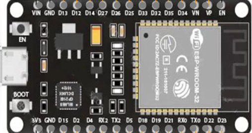
Pin Configuration and Descriptions

The ESP32 has multiple GPIO pins, which are multifunctional and can be configured for various purposes. Below is a general pinout description for the ESP32 development board:

Pin Name Description
1 3V3 3.3V power supply output
2 GND Ground
3 EN Enable pin (active high, used to reset the chip)
4 GPIO0 General-purpose I/O, boot mode selection during startup
5 GPIO2 General-purpose I/O, often used for onboard LED
6-11 GPIO12-19 General-purpose I/O, configurable for ADC, PWM, I2C, SPI, etc.
12 TX0 (GPIO1) UART0 Transmit
13 RX0 (GPIO3) UART0 Receive
14 ADC1_CH0 Analog input channel 0
15 DAC1 (GPIO25) Digital-to-Analog Converter output
16 DAC2 (GPIO26) Digital-to-Analog Converter output
17 GPIO34-39 Input-only pins, often used for analog inputs

Note: The exact pinout may vary depending on the ESP32 module or development board you are using. Always refer to the datasheet or schematic for your specific board.

Usage Instructions

How to Use the ESP32 in a Circuit

  1. Power Supply: Provide a stable 3.3V power supply to the ESP32. Avoid exceeding this voltage to prevent damage.
  2. Boot Mode: Connect GPIO0 to GND during startup to enter bootloader mode for programming.
  3. Peripherals: Use the GPIO pins for interfacing with sensors, actuators, and other devices. Configure the pins in your code as needed.
  4. Programming: The ESP32 can be programmed using the Arduino IDE, Espressif's ESP-IDF, or other compatible tools.

Example: Connecting ESP32 to an Arduino IDE

  1. Install the ESP32 board package in the Arduino IDE.
  2. Connect the ESP32 to your computer via USB.
  3. Select the correct board and port in the Arduino IDE.
  4. Upload the following example code to blink an onboard LED:
// Example: Blink an onboard LED on ESP32

// Define the GPIO pin connected to the onboard LED
#define LED_PIN 2

void setup() {
  pinMode(LED_PIN, OUTPUT); // Set the LED pin as an output
}

void loop() {
  digitalWrite(LED_PIN, HIGH); // Turn the LED on
  delay(1000);                 // Wait for 1 second
  digitalWrite(LED_PIN, LOW);  // Turn the LED off
  delay(1000);                 // Wait for 1 second
}

Important Considerations and Best Practices

  • Voltage Levels: Ensure all connected peripherals operate at 3.3V logic levels. Use level shifters if needed.
  • Power Supply: Use a decoupling capacitor near the power pins to stabilize the voltage.
  • Wi-Fi Interference: Avoid placing the ESP32 near sources of electromagnetic interference to maintain reliable Wi-Fi performance.
  • Heat Management: The ESP32 may heat up during operation. Ensure proper ventilation or heat dissipation if used in high-performance applications.

Troubleshooting and FAQs

Common Issues and Solutions

  1. ESP32 Not Detected by Computer

    • Ensure the USB cable is functional and supports data transfer.
    • Install the correct USB-to-serial driver for your ESP32 board.
  2. Upload Fails with "Failed to Connect" Error

    • Check that GPIO0 is connected to GND during bootloader mode.
    • Press and hold the "BOOT" button on the ESP32 while uploading the code.
  3. Wi-Fi Connection Issues

    • Verify the SSID and password in your code.
    • Ensure the Wi-Fi network operates on the 2.4 GHz band (ESP32 does not support 5 GHz).
  4. Random Resets or Instability

    • Check the power supply for sufficient current (at least 500 mA recommended).
    • Add decoupling capacitors to stabilize the power supply.

FAQs

Q: Can the ESP32 operate on battery power?
A: Yes, the ESP32 supports low-power modes, making it suitable for battery-powered applications. Use a 3.7V LiPo battery with a voltage regulator to provide 3.3V.

Q: How do I update the firmware on the ESP32?
A: Use the Espressif Flash Download Tool or the Arduino IDE to upload new firmware. Ensure the ESP32 is in bootloader mode during the process.

Q: Can I use the ESP32 with sensors that operate at 5V?
A: Yes, but you will need level shifters to safely interface 5V sensors with the ESP32's 3.3V GPIO pins.

Q: Does the ESP32 support over-the-air (OTA) updates?
A: Yes, the ESP32 supports OTA updates, allowing you to update firmware wirelessly.

By following this documentation, you can effectively integrate the ESP32 into your projects and troubleshoot common issues.