Cirkit Designer Logo
Cirkit Designer
Your all-in-one circuit design IDE
Home / 
Component Documentation

How to Use PmodHB5_Driver: Examples, Pinouts, and Specs

Image of PmodHB5_Driver
Cirkit Designer LogoDesign with PmodHB5_Driver in Cirkit Designer

Introduction

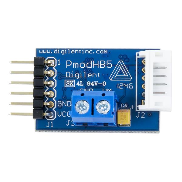
The PmodHB5 Driver is a versatile motor driver module capable of driving DC motors with an output current of up to 5A. It is designed to be interfaced with microcontrollers such as the Arduino UNO and can be controlled using digital PWM (Pulse Width Modulation) signals. This module is ideal for applications requiring precise motor speed and direction control, such as robotics, automated machinery, and educational projects.

Explore Projects Built with PmodHB5_Driver

Use Cirkit Designer to design, explore, and prototype these projects online. Some projects support real-time simulation. Click "Open Project" to start designing instantly!
Dual Hub Motor Control System with USB to TTL Interface and Relay Switching
Image of Hub Motor & servo motor Connection: A project utilizing PmodHB5_Driver in a practical application
This circuit is designed to control two hub motors using a HUB driver, powered by a DC-DC converter and a power module. The USB to TTL converter allows for communication with the HUB driver, and a 5V relay module is used to switch the motors on and off.
Cirkit Designer LogoOpen Project in Cirkit Designer
Transistor-Based Motor Speed Regulation Circuit
Image of H Bridge Project: A project utilizing PmodHB5_Driver in a practical application
This circuit appears to be a H-bridge motor driver using a combination of PNP and NPN transistors to control the direction of a DC motor. The 5V battery is connected to the emitters of the PNP transistors and the 9V batteries are connected through resistors to the bases of the transistors, likely for biasing purposes. The arrangement allows the motor to be driven in both directions by selectively activating the transistors.
Cirkit Designer LogoOpen Project in Cirkit Designer
Bluetooth-Controlled Robotic Car with L293D Motor Driver and HC-05 Module
Image of Bluetooth: A project utilizing PmodHB5_Driver in a practical application
This circuit is a Bluetooth-controlled motor driver system using an L293D driver shield and an HC-05 Bluetooth module. The system controls four hobby motors, allowing for forward, backward, left, and right movements based on commands received via Bluetooth.
Cirkit Designer LogoOpen Project in Cirkit Designer
ESP32-Powered Wi-Fi Controlled Robotic Car with OLED Display and Ultrasonic Sensor
Image of playbot: A project utilizing PmodHB5_Driver in a practical application
This circuit is a battery-powered system featuring an ESP32 microcontroller that controls an OLED display, a motor driver for two hobby motors, an ultrasonic sensor for distance measurement, and a DFPlayer Mini for audio output through a loudspeaker. The TP4056 module manages battery charging, and a step-up boost converter provides a stable 5V supply to the components.
Cirkit Designer LogoOpen Project in Cirkit Designer

Explore Projects Built with PmodHB5_Driver

Use Cirkit Designer to design, explore, and prototype these projects online. Some projects support real-time simulation. Click "Open Project" to start designing instantly!
Image of Hub Motor & servo motor Connection: A project utilizing PmodHB5_Driver in a practical application
Dual Hub Motor Control System with USB to TTL Interface and Relay Switching
This circuit is designed to control two hub motors using a HUB driver, powered by a DC-DC converter and a power module. The USB to TTL converter allows for communication with the HUB driver, and a 5V relay module is used to switch the motors on and off.
Cirkit Designer LogoOpen Project in Cirkit Designer
Image of H Bridge Project: A project utilizing PmodHB5_Driver in a practical application
Transistor-Based Motor Speed Regulation Circuit
This circuit appears to be a H-bridge motor driver using a combination of PNP and NPN transistors to control the direction of a DC motor. The 5V battery is connected to the emitters of the PNP transistors and the 9V batteries are connected through resistors to the bases of the transistors, likely for biasing purposes. The arrangement allows the motor to be driven in both directions by selectively activating the transistors.
Cirkit Designer LogoOpen Project in Cirkit Designer
Image of Bluetooth: A project utilizing PmodHB5_Driver in a practical application
Bluetooth-Controlled Robotic Car with L293D Motor Driver and HC-05 Module
This circuit is a Bluetooth-controlled motor driver system using an L293D driver shield and an HC-05 Bluetooth module. The system controls four hobby motors, allowing for forward, backward, left, and right movements based on commands received via Bluetooth.
Cirkit Designer LogoOpen Project in Cirkit Designer
Image of playbot: A project utilizing PmodHB5_Driver in a practical application
ESP32-Powered Wi-Fi Controlled Robotic Car with OLED Display and Ultrasonic Sensor
This circuit is a battery-powered system featuring an ESP32 microcontroller that controls an OLED display, a motor driver for two hobby motors, an ultrasonic sensor for distance measurement, and a DFPlayer Mini for audio output through a loudspeaker. The TP4056 module manages battery charging, and a step-up boost converter provides a stable 5V supply to the components.
Cirkit Designer LogoOpen Project in Cirkit Designer

Common Applications and Use Cases

  • Robotics: Driving motors for robotic arms, wheels, or tracks.
  • Automation: Controlling conveyor belts, pumps, or fans.
  • Educational Projects: Teaching motor control principles in STEM education.
  • Hobby Projects: DIY projects requiring motor control, such as model vehicles.

Technical Specifications

Key Technical Details

  • Operating Voltage: 4.5V to 16V
  • Output Current: Up to 5A
  • Control Signal: Digital PWM
  • Direction Control: Forward and Reverse
  • Protection Features: Overcurrent and thermal protection

Pin Configuration and Descriptions

Pin Number Pin Name Description
1 VCC Power supply input (4.5V to 16V)
2 GND Ground connection
3 PWM PWM input for speed control
4 DIR Direction control input (High/Low)
5 SLEEP Sleep mode enable (Active Low)
6 FAULT Fault indication output (Active Low)

Usage Instructions

How to Use the PmodHB5 in a Circuit

  1. Power Connections: Connect the VCC pin to a suitable power supply (4.5V to 16V) and the GND pin to the ground.
  2. Motor Connections: Attach the motor leads to the output terminals of the PmodHB5.
  3. Control Signal: Generate a PWM signal from your microcontroller and connect it to the PWM pin for speed control.
  4. Direction Control: Set the DIR pin high or low to control the motor's direction.
  5. Sleep Mode: Optionally, connect the SLEEP pin to a digital output on your microcontroller to enable or disable the driver.
  6. Fault Detection: Monitor the FAULT pin to detect any fault conditions such as overcurrent or overheating.

Important Considerations and Best Practices

  • Ensure the power supply can handle the motor's current requirements.
  • Use a decoupling capacitor close to the PmodHB5's power input to minimize voltage spikes.
  • Avoid running the motor at full current for extended periods to prevent overheating.
  • Implement an adequate cooling system if operating near the maximum current rating.
  • Always check the motor's specifications to ensure compatibility with the driver's capabilities.

Example Code for Arduino UNO

// Define the pins connected to the PmodHB5
const int pwmPin = 3;   // PWM input for speed control
const int dirPin = 4;   // Direction control input

void setup() {
  // Set the motor control pins as outputs
  pinMode(pwmPin, OUTPUT);
  pinMode(dirPin, OUTPUT);
}

void loop() {
  // Set motor direction to forward
  digitalWrite(dirPin, HIGH);
  
  // Ramp up the motor speed
  for (int speed = 0; speed <= 255; speed++) {
    analogWrite(pwmPin, speed);
    delay(10);
  }
  
  // Ramp down the motor speed
  for (int speed = 255; speed >= 0; speed--) {
    analogWrite(pwmPin, speed);
    delay(10);
  }
  
  // Change motor direction to reverse
  digitalWrite(dirPin, LOW);
  
  // Repeat the ramp up and ramp down process
  // ...
}

Troubleshooting and FAQs

Common Issues

  • Motor not running: Check power supply connections and ensure the PWM signal is being generated.
  • Overheating: Ensure the motor's current draw is within the module's limits and improve cooling if necessary.
  • Fault indicator active: Check for overcurrent conditions or wiring errors.

Solutions and Tips for Troubleshooting

  • Verify all connections are secure and correct.
  • Use a multimeter to check the power supply voltage and motor resistance.
  • Ensure the PWM frequency is within the acceptable range for the PmodHB5.
  • If the FAULT pin is active, disconnect the power and inspect the motor and driver for any signs of damage.

FAQs

Q: Can I control two motors with one PmodHB5? A: No, the PmodHB5 is designed to control one motor at a time.

Q: What is the maximum PWM frequency the PmodHB5 can handle? A: Please refer to the datasheet for the maximum PWM frequency specifications.

Q: How do I know if the PmodHB5 is in fault mode? A: The FAULT pin will be pulled low when a fault is detected. Monitoring this pin with a microcontroller can alert you to any issues.

Q: Can I use the PmodHB5 with a 3.3V logic level microcontroller? A: Yes, but ensure that the logic level is compatible with the PmodHB5's input thresholds. Use a level shifter if necessary.