How to Use AdaGator Side Blue: Examples, Pinouts, and Specs
Introduction
The AdaGator Side Blue is a modular circuit component designed for use within Adafruit's AdaGator ecosystem. This blue-colored side piece serves as a connector, enabling the integration of various components in a streamlined and aesthetically pleasing manner. It is commonly used in DIY electronics projects, educational settings, and by hobbyists who require a reliable and easy-to-use system for building electronic circuits.
Explore Projects Built with AdaGator Side Blue


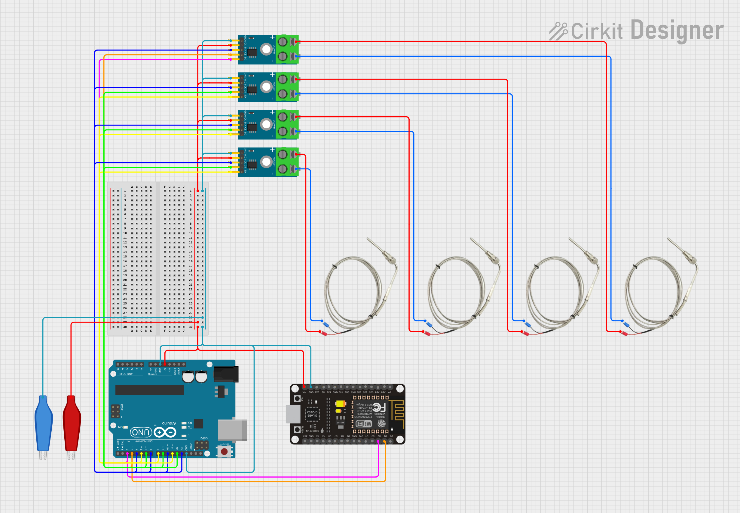
Explore Projects Built with AdaGator Side Blue
Common Applications and Use Cases
- Prototyping electronic circuits
- Educational projects for learning electronics
- DIY electronics and maker projects
- Custom-built gadgets and devices
Technical Specifications
The AdaGator Side Blue is designed to be compatible with the AdaGator system and does not have electrical specifications in the traditional sense. However, its mechanical and physical characteristics are crucial for proper integration with other components.
Pin Configuration and Descriptions
| Pin Number | Description | Notes |
|---|---|---|
| 1 | Mechanical Lock | Secures to adjacent components |
| 2 | Alignment Guide | Ensures proper orientation |
| 3 | Data Connection (if applicable) | For components that transfer data |
| 4 | Power Connection (if applicable) | For components that require power |
| 5 | Ground Connection (if applicable) | Common ground for circuit integrity |
Note: The AdaGator Side Blue may not have active electrical connections and is primarily used for mechanical stability and aesthetics.
Usage Instructions
How to Use the Component in a Circuit
Preparation:
- Ensure all components to be connected are part of the AdaGator system and are compatible with the AdaGator Side Blue.
- Gather all necessary tools and components before starting the assembly.
Assembly:
- Align the AdaGator Side Blue with the adjacent component, following the orientation indicated by the Alignment Guide (Pin 2).
- Gently press the AdaGator Side Blue into place until the Mechanical Lock (Pin 1) clicks, indicating a secure connection.
Integration:
- If the AdaGator Side Blue includes data, power, or ground connections, ensure that these are properly aligned and connected to the corresponding pins on the adjacent component.
Important Considerations and Best Practices
- Do not force the AdaGator Side Blue into place; this may damage the Mechanical Lock or the Alignment Guide.
- Ensure that the component is free from dust and debris before assembly to maintain a good connection.
- If the AdaGator Side Blue is part of a powered circuit, always disconnect the power source before making adjustments to avoid electric shock or damage to the components.
Troubleshooting and FAQs
Common Issues Users Might Face
- Difficulty in Assembly: Ensure that the pins are correctly aligned and that no debris is obstructing the connection.
- Loose Connections: If the AdaGator Side Blue becomes loose, check the Mechanical Lock for signs of wear or damage.
Solutions and Tips for Troubleshooting
- Misalignment: Double-check the orientation using the Alignment Guide and reattempt the connection.
- Wear and Tear: If the Mechanical Lock is damaged, consider replacing the AdaGator Side Blue to ensure a secure fit.
FAQs
Q: Can the AdaGator Side Blue be used with non-AdaGator components?
A: The AdaGator Side Blue is designed specifically for the AdaGator system and may not be compatible with other components.
Q: Does the AdaGator Side Blue conduct electricity?
A: The AdaGator Side Blue is primarily a mechanical component and may not have active electrical connections. Check the product specifications for details on any electrical functionality.
Q: How do I remove the AdaGator Side Blue from a circuit?
A: Gently press on the release mechanism of the Mechanical Lock and carefully pull the AdaGator Side Blue away from the adjacent component.
Q: Is the AdaGator Side Blue reusable?
A: Yes, the AdaGator Side Blue is designed to be reusable, provided it is not damaged during removal or use.
Note: This documentation is based on a hypothetical component named "AdaGator Side Blue" and is for illustrative purposes only.