Cirkit Designer
Your all-in-one circuit design IDE
Home /
Component Documentation
How to Use Single Channel 12 V Relay Module: Examples, Pinouts, and Specs
Introduction
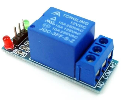
The Single Channel 12V Relay Module is an essential component for interfacing low-power microcontrollers with high-power devices. This relay module allows a microcontroller, such as an Arduino, to control devices operating at 12 volts, making it ideal for switching AC or DC loads. Common applications include home automation, industrial control systems, and various DIY electronics projects.
Explore Projects Built with Single Channel 12 V Relay Module
DC-DC Converter and Relay Module Power Distribution System

This circuit consists of a DC-DC converter powering a 6-channel power module, which in turn supplies 5V to a 2-relay module. The power module distributes the converted voltage to the relay module, enabling it to control external devices.
Battery-Powered 4-Channel Relay Control with LED Indicators

This circuit consists of a 5V battery powering a 4-channel relay module, which controls four LEDs (red, yellow, green, and blue) through individual resistors. Each relay channel is activated by a corresponding SPST toggle switch, allowing manual control of the LEDs.
Battery-Powered IR Sensor Controlled Relay Module

This circuit uses an IR sensor to control a 1 Channel 5V Relay Module, which is powered by a 9V battery. The IR sensor detects an object and sends a signal to the relay module to switch its state, enabling or disabling the connected load.
Wi-Fi Controlled Relay System Using ESP8266

This circuit uses an ESP8266 microcontroller to control a 4-channel relay module, which can switch various loads. The ESP8266 is powered by a 12V DC supply converted from an AC source, and it interfaces with the relay module to control the relays via its digital output pins.
Explore Projects Built with Single Channel 12 V Relay Module
DC-DC Converter and Relay Module Power Distribution System
This circuit consists of a DC-DC converter powering a 6-channel power module, which in turn supplies 5V to a 2-relay module. The power module distributes the converted voltage to the relay module, enabling it to control external devices.
Battery-Powered 4-Channel Relay Control with LED Indicators
This circuit consists of a 5V battery powering a 4-channel relay module, which controls four LEDs (red, yellow, green, and blue) through individual resistors. Each relay channel is activated by a corresponding SPST toggle switch, allowing manual control of the LEDs.
Battery-Powered IR Sensor Controlled Relay Module
This circuit uses an IR sensor to control a 1 Channel 5V Relay Module, which is powered by a 9V battery. The IR sensor detects an object and sends a signal to the relay module to switch its state, enabling or disabling the connected load.
Wi-Fi Controlled Relay System Using ESP8266
This circuit uses an ESP8266 microcontroller to control a 4-channel relay module, which can switch various loads. The ESP8266 is powered by a 12V DC supply converted from an AC source, and it interfaces with the relay module to control the relays via its digital output pins.
Technical Specifications
Key Technical Details
| Parameter | Value |
|---|---|
| Operating Voltage | 12V DC |
| Trigger Voltage | 5V DC (from microcontroller) |
| Current Consumption | 20mA (standby), 70mA (active) |
| Relay Type | SPDT (Single Pole Double Throw) |
| Max Switching Voltage | 250V AC / 30V DC |
| Max Switching Current | 10A |
| Dimensions | 50mm x 26mm x 18.5mm |
Pin Configuration and Descriptions
| Pin Name | Description |
|---|---|
| VCC | Connect to 12V DC power supply |
| GND | Ground |
| IN | Control signal from microcontroller (5V logic) |
| NO | Normally Open contact |
| COM | Common contact |
| NC | Normally Closed contact |
Usage Instructions
How to Use the Component in a Circuit
Power Supply:
- Connect the VCC pin to a 12V DC power supply.
- Connect the GND pin to the ground of the power supply.
Control Signal:
- Connect the IN pin to a digital output pin of the microcontroller (e.g., Arduino).
Load Connection:
- Connect the device you want to control to the NO (Normally Open) and COM (Common) pins if you want the device to be off by default and turn on when the relay is activated.
- Alternatively, connect the device to the NC (Normally Closed) and COM (Common) pins if you want the device to be on by default and turn off when the relay is activated.
Important Considerations and Best Practices
- Ensure that the power supply voltage matches the relay module's operating voltage (12V DC).
- Do not exceed the maximum switching voltage and current ratings to avoid damaging the relay.
- Use a flyback diode across the relay coil to protect the microcontroller from voltage spikes.
- Keep the control signal wire as short as possible to minimize noise and interference.
Example Code for Arduino UNO
/*
  Single Channel 12V Relay Module Control
  This example code demonstrates how to control a 12V relay module
  using an Arduino UNO. The relay will turn on for 2 seconds and
  then turn off for 2 seconds in a loop.
*/

const int relayPin = 7; // Pin connected to IN pin of relay module

void setup() {
  pinMode(relayPin, OUTPUT); // Set relay pin as an output
}

void loop() {
  digitalWrite(relayPin, HIGH); // Turn relay on
  delay(2000); // Wait for 2 seconds
  digitalWrite(relayPin, LOW); // Turn relay off
  delay(2000); // Wait for 2 seconds
}
Troubleshooting and FAQs
Common Issues Users Might Face
Relay Not Activating:
- Ensure the control signal voltage is 5V.
- Check the power supply voltage (12V DC) and connections.
- Verify that the microcontroller pin is set as an output.
Relay Stuck in One State:
- Check for any short circuits or loose connections.
- Ensure the load does not exceed the relay's maximum ratings.
Interference and Noise:
- Use a flyback diode across the relay coil.
- Keep control signal wires short and away from high-power lines.
Solutions and Tips for Troubleshooting
- Check Connections: Double-check all wiring and connections to ensure they are secure and correct.
- Use Proper Power Supply: Make sure the power supply provides a stable 12V DC output.
- Test with Multimeter: Use a multimeter to verify voltages at various points in the circuit.
- Isolate Issues: Test the relay module separately from the rest of the circuit to isolate the problem.
By following this documentation, users can effectively integrate the Single Channel 12V Relay Module into their projects, ensuring reliable and efficient control of high-power devices with a low-power microcontroller.