How to Use ESP wroom 32 (30 pines): Examples, Pinouts, and Specs
Introduction
The ESP-WROOM-32 is a powerful microcontroller module designed for IoT (Internet of Things) applications. It features built-in Wi-Fi and Bluetooth capabilities, making it ideal for wireless communication and control. With 30 GPIO pins, the ESP-WROOM-32 offers versatile connectivity options for sensors, actuators, and other peripherals. Its compact size and robust performance make it a popular choice for smart home devices, industrial automation, and wearable technology.
Explore Projects Built with ESP wroom 32 (30 pines)


Explore Projects Built with ESP wroom 32 (30 pines)
Common Applications:
- Smart home automation (e.g., lighting, thermostats, security systems)
- IoT devices and wireless sensor networks
- Wearable technology
- Industrial automation and control systems
- Robotics and remote monitoring systems
Technical Specifications
Key Technical Details:
| Parameter | Value |
|---|---|
| Microcontroller | Tensilica Xtensa LX6 Dual-Core Processor |
| Clock Speed | Up to 240 MHz |
| Flash Memory | 4 MB (varies by model) |
| SRAM | 520 KB |
| Wi-Fi Standard | 802.11 b/g/n |
| Bluetooth Version | Bluetooth v4.2 (Classic + BLE) |
| Operating Voltage | 3.3V |
| GPIO Pins | 30 |
| ADC Channels | 18 (12-bit resolution) |
| DAC Channels | 2 |
| Communication Interfaces | UART, SPI, I2C, I2S, CAN, PWM |
| Power Consumption | 5 µA (deep sleep), ~80 mA (active Wi-Fi) |
| Operating Temperature | -40°C to 85°C |
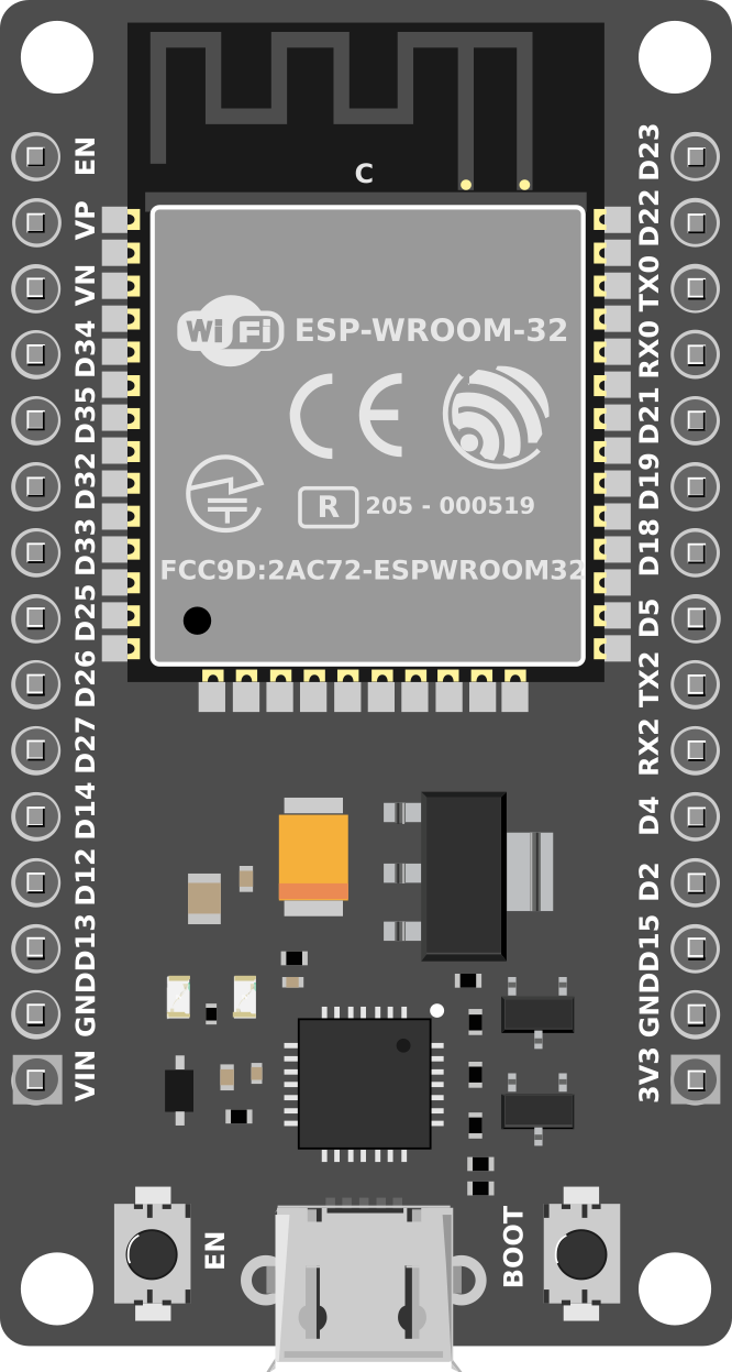
Pin Configuration and Descriptions:
The ESP-WROOM-32 module has 30 pins, each with specific functions. Below is the pinout description:
| Pin Number | Pin Name | Functionality |
|---|---|---|
| 1 | EN | Enable pin (active high, resets the chip when pulled low) |
| 2 | IO0 | GPIO0, used for boot mode selection (must be low during flashing) |
| 3 | IO1 (TX0) | GPIO1, UART0 TX (default serial output) |
| 4 | IO3 (RX0) | GPIO3, UART0 RX (default serial input) |
| 5 | IO4 | GPIO4, general-purpose I/O |
| 6 | IO5 | GPIO5, general-purpose I/O |
| 7 | IO12 | GPIO12, ADC2 channel 5, touch sensor 2 |
| 8 | IO13 | GPIO13, ADC2 channel 4, touch sensor 3 |
| 9 | IO14 | GPIO14, ADC2 channel 6, touch sensor 4 |
| 10 | IO15 | GPIO15, ADC2 channel 3, touch sensor 5 |
| 11 | IO16 | GPIO16, general-purpose I/O |
| 12 | IO17 | GPIO17, general-purpose I/O |
| 13 | IO18 | GPIO18, SPI clock (SCK) |
| 14 | IO19 | GPIO19, SPI MISO |
| 15 | IO21 | GPIO21, I2C SDA |
| 16 | IO22 | GPIO22, I2C SCL |
| 17 | IO23 | GPIO23, SPI MOSI |
| 18 | IO25 | GPIO25, DAC1, ADC2 channel 8 |
| 19 | IO26 | GPIO26, DAC2, ADC2 channel 9 |
| 20 | IO27 | GPIO27, ADC2 channel 7 |
| 21 | IO32 | GPIO32, ADC1 channel 4, touch sensor 9 |
| 22 | IO33 | GPIO33, ADC1 channel 5, touch sensor 8 |
| 23 | IO34 | GPIO34, ADC1 channel 6 (input only) |
| 24 | IO35 | GPIO35, ADC1 channel 7 (input only) |
| 25 | GND | Ground |
| 26 | 3V3 | 3.3V power supply |
| 27 | VIN | Input voltage (5V) |
| 28 | IO36 (VP) | GPIO36, ADC1 channel 0 (input only) |
| 29 | IO39 (VN) | GPIO39, ADC1 channel 3 (input only) |
| 30 | RST | Reset pin (active low) |
Usage Instructions
How to Use the ESP-WROOM-32 in a Circuit:
- Power Supply: Provide a stable 3.3V power supply to the
3V3pin. Alternatively, you can supply 5V to theVINpin, which is regulated internally. - Programming: Use a USB-to-serial adapter or development board (e.g., ESP32 DevKit) to program the module. Ensure GPIO0 is pulled low during flashing.
- Connections: Connect peripherals (e.g., sensors, actuators) to the GPIO pins. Use pull-up or pull-down resistors as needed.
- Communication: Utilize UART, SPI, or I2C interfaces for communication with other devices.
- Antenna: Ensure the onboard antenna has sufficient clearance for optimal Wi-Fi and Bluetooth performance.
Important Considerations:
- Voltage Levels: All GPIO pins operate at 3.3V logic levels. Avoid applying 5V directly to any pin.
- Boot Mode: During flashing, GPIO0 must be pulled low, and the EN pin must be toggled.
- Power Consumption: Use deep sleep mode to minimize power usage in battery-powered applications.
- Heat Management: Ensure proper ventilation or heat dissipation for high-performance applications.
Example Code for Arduino UNO:
Below is an example of using the ESP-WROOM-32 to connect to a Wi-Fi network and print the IP address:
#include <WiFi.h> // Include the WiFi library for ESP32

const char* ssid = "Your_SSID";       // Replace with your Wi-Fi SSID
const char* password = "Your_Password"; // Replace with your Wi-Fi password

void setup() {
  Serial.begin(115200); // Initialize serial communication at 115200 baud
  delay(1000);          // Wait for serial monitor to initialize

  Serial.println("Connecting to Wi-Fi...");
  WiFi.begin(ssid, password); // Start Wi-Fi connection

  while (WiFi.status() != WL_CONNECTED) {
    delay(500); // Wait for connection
    Serial.print(".");
  }

  Serial.println("\nWi-Fi connected!");
  Serial.print("IP Address: ");
  Serial.println(WiFi.localIP()); // Print the assigned IP address
}

void loop() {
  // Add your main code here
}
Troubleshooting and FAQs
Common Issues:
- Module Not Responding:
- Ensure the EN pin is pulled high.
- Check the power supply voltage (3.3V or 5V on VIN).
- Wi-Fi Connection Fails:
- Verify the SSID and password.
- Check for interference or weak signal strength.
- Flashing Errors:
- Ensure GPIO0 is pulled low during flashing.
- Use a reliable USB-to-serial adapter with proper drivers installed.
Solutions and Tips:
- Use a multimeter to verify power supply and pin connections.
- Update the ESP32 board package in the Arduino IDE to the latest version.
- For debugging, use
Serial.print()statements to monitor the program flow.
This documentation provides a comprehensive guide to using the ESP-WROOM-32 module effectively. For further assistance, refer to the official datasheet or community forums.