How to Use buzzer: Examples, Pinouts, and Specs
Introduction
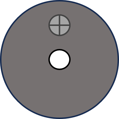
A buzzer, manufactured by JJY with part ID bz, is an audio signaling device that produces sound when an electric current passes through it. Buzzers are widely used in various applications, including alarms, timers, and notification systems, due to their simplicity and reliability. They are available in different types, such as piezoelectric and electromagnetic buzzers, and are commonly found in consumer electronics, automotive systems, and industrial equipment.
Explore Projects Built with buzzer
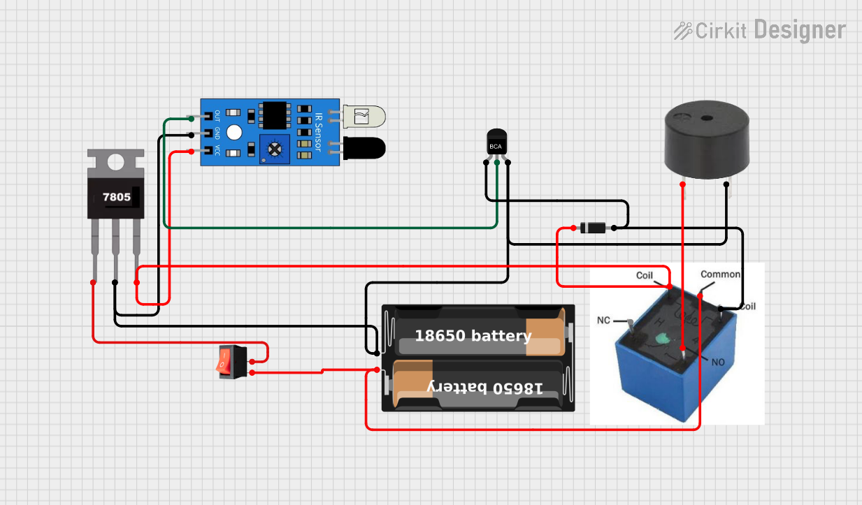
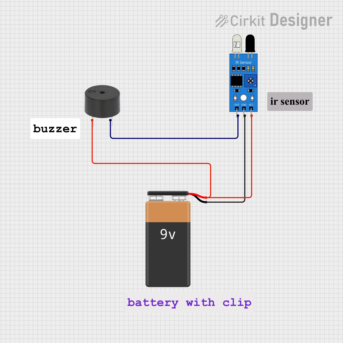

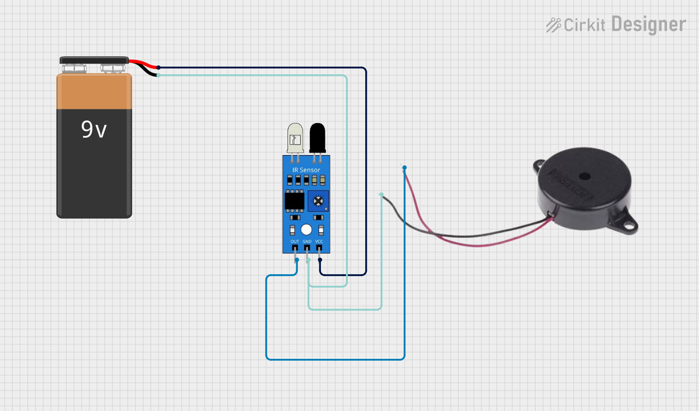
Explore Projects Built with buzzer
Common Applications
- Alarm systems (e.g., fire alarms, security alarms)
- Timers and reminders
- Notification systems in appliances (e.g., microwave ovens, washing machines)
- Feedback indicators in user interfaces (e.g., button presses)
- Toys and educational projects
Technical Specifications
Key Technical Details
| Parameter | Value |
|---|---|
| Manufacturer | JJY |
| Part ID | bz |
| Operating Voltage | 3V to 12V DC |
| Current Consumption | 10mA to 30mA (depending on voltage) |
| Sound Output Level | 85dB at 10cm (typical) |
| Frequency Range | 2kHz to 4kHz |
| Operating Temperature | -20°C to +70°C |
| Dimensions | 12mm diameter, 8mm height |
| Type | Piezoelectric or Electromagnetic |
Pin Configuration and Descriptions
| Pin Number | Pin Name | Description |
|---|---|---|
| 1 | VCC | Positive terminal for power supply (3V to 12V DC) |
| 2 | GND | Ground terminal for power supply |
Usage Instructions
How to Use the Buzzer in a Circuit
- Power Supply: Connect the
VCCpin of the buzzer to a DC power source (3V to 12V) and theGNDpin to the ground of the circuit. - Control Signal: To control the buzzer, you can use a microcontroller (e.g., Arduino UNO) or a simple switch. For microcontroller-based control, connect the
VCCpin to a digital output pin and toggle it HIGH or LOW to turn the buzzer ON or OFF. - Resistor (Optional): If the buzzer draws more current than the microcontroller pin can handle, use a current-limiting resistor or a transistor as a driver.
Important Considerations and Best Practices
- Voltage Range: Ensure the operating voltage is within the specified range (3V to 12V). Exceeding this range may damage the buzzer.
- Polarity: Observe correct polarity when connecting the buzzer. Reversing the connections may result in malfunction or permanent damage.
- Mounting: Secure the buzzer in place to prevent vibrations from affecting its performance.
- Noise Sensitivity: Avoid placing the buzzer near sensitive components that may be affected by its sound or vibrations.
Example: Connecting the Buzzer to an Arduino UNO
Below is an example of how to connect and control the buzzer using an Arduino UNO:
// Example: Controlling a buzzer with Arduino UNO
// Connect the buzzer's VCC pin to Arduino pin 8 and GND pin to Arduino GND.

#define BUZZER_PIN 8  // Define the pin connected to the buzzer

void setup() {
  pinMode(BUZZER_PIN, OUTPUT);  // Set the buzzer pin as an output
}

void loop() {
  digitalWrite(BUZZER_PIN, HIGH);  // Turn the buzzer ON
  delay(1000);                     // Wait for 1 second
  digitalWrite(BUZZER_PIN, LOW);   // Turn the buzzer OFF
  delay(1000);                     // Wait for 1 second
}
Troubleshooting and FAQs
Common Issues and Solutions
No Sound from the Buzzer
- Cause: Incorrect wiring or insufficient voltage.
- Solution: Verify the connections and ensure the power supply voltage is within the specified range.
Buzzer Produces Weak or Distorted Sound
- Cause: Low supply voltage or interference from nearby components.
- Solution: Check the power supply and ensure it provides sufficient current. Relocate the buzzer away from noise-sensitive components.
Buzzer Does Not Turn Off
- Cause: Faulty control signal or short circuit.
- Solution: Inspect the control circuit and ensure the microcontroller pin is functioning correctly.
Buzzer Overheats
- Cause: Exceeding the maximum voltage or current rating.
- Solution: Use a resistor or transistor to limit the current and ensure the voltage is within the specified range.
FAQs
Q: Can I use the buzzer with an AC power source?
A: No, the buzzer is designed for DC power only. Using AC power may damage the component.Q: How can I adjust the sound volume of the buzzer?
A: The volume is fixed for most buzzers. However, you can reduce the supply voltage slightly to lower the volume, but ensure it remains within the operating range.Q: Can I use the buzzer for generating different tones?
A: Yes, if the buzzer is a piezoelectric type, you can generate different tones by varying the frequency of the control signal.Q: Is the buzzer waterproof?
A: No, this buzzer is not waterproof. Avoid exposing it to moisture or water.
By following this documentation, you can effectively integrate the JJY bz buzzer into your projects and troubleshoot common issues with ease.