How to Use BMX 160: Examples, Pinouts, and Specs
Introduction
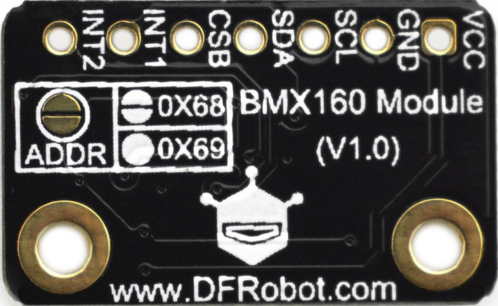
The BMX 160 (Manufacturer Part ID: SEN0373) is a high-performance DC-DC converter designed by DFRobot. It is engineered for efficient voltage regulation in a variety of electronic applications. With its compact design, high efficiency, and wide input voltage range, the BMX 160 is ideal for powering sensitive electronic devices, ensuring stable and reliable operation.
Explore Projects Built with BMX 160
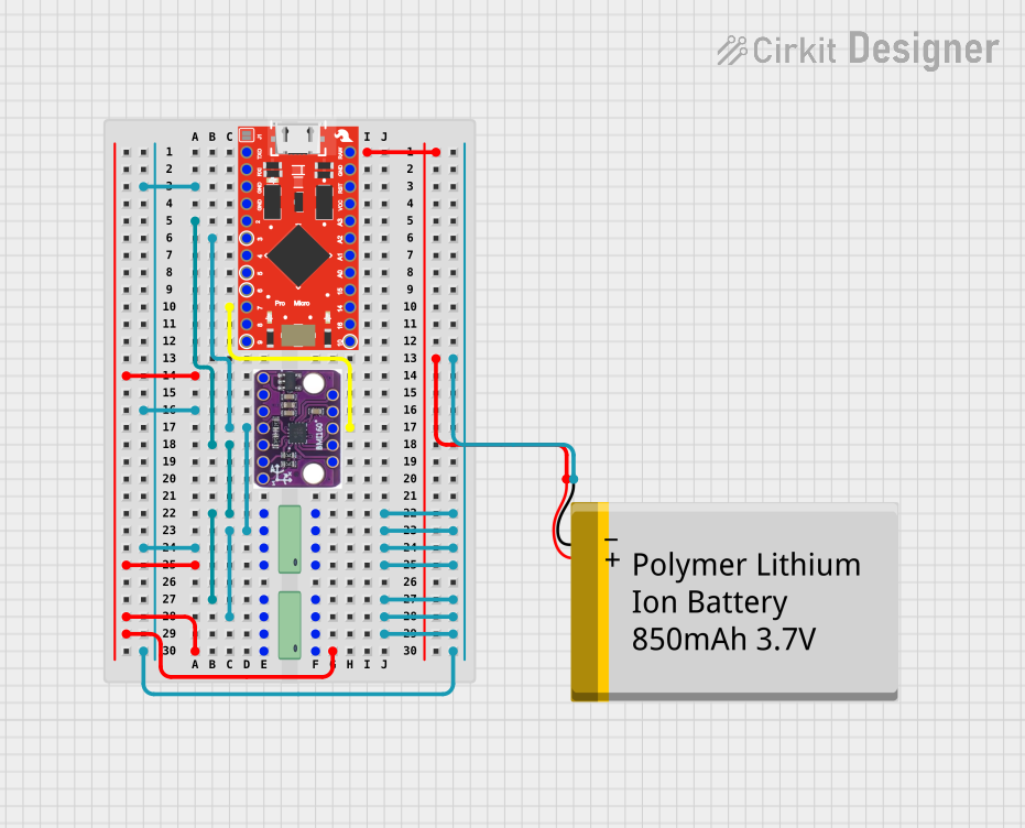
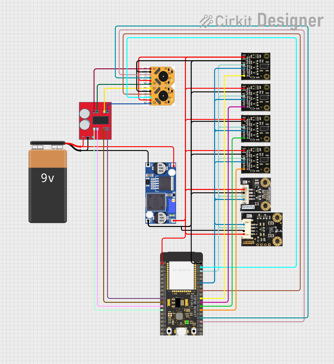
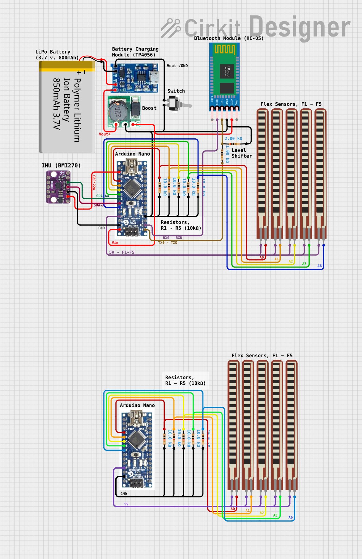
Explore Projects Built with BMX 160
Common Applications and Use Cases
- Powering microcontrollers, sensors, and other low-power devices
- Voltage regulation in battery-powered systems
- Applications requiring high efficiency and minimal heat generation
- Portable electronics and IoT devices
- Robotics and automation systems
Technical Specifications
The BMX 160 is designed to deliver reliable performance under a wide range of operating conditions. Below are its key technical specifications:
| Parameter | Value |
|---|---|
| Input Voltage Range | 4.5V to 28V |
| Output Voltage Range | 0.8V to 20V |
| Output Current | Up to 3A |
| Efficiency | Up to 95% |
| Switching Frequency | 1.2 MHz |
| Operating Temperature | -40°C to +85°C |
| Dimensions | 22mm x 17mm x 4mm |
Pin Configuration and Descriptions
The BMX 160 features a simple pinout for easy integration into circuits. Below is the pin configuration:
| Pin | Name | Description |
|---|---|---|
| 1 | VIN | Input voltage pin (4.5V to 28V) |
| 2 | GND | Ground connection |
| 3 | VOUT | Regulated output voltage pin (0.8V to 20V) |
| 4 | EN | Enable pin (active high, logic level to enable) |
| 5 | FB | Feedback pin for output voltage adjustment |
Usage Instructions
The BMX 160 is straightforward to use in a circuit. Follow the steps below to integrate it into your design:
Basic Circuit Connection
- Input Voltage: Connect the input voltage source (4.5V to 28V) to the
VINpin. - Ground: Connect the
GNDpin to the ground of your circuit. - Output Voltage: Connect the load to the
VOUTpin. Ensure the load does not exceed the maximum output current of 3A. - Enable Pin: To enable the converter, apply a logic high signal (e.g., 3.3V or 5V) to the
ENpin. Leave it unconnected or pull it low to disable the converter. - Feedback Pin: Use a resistor divider network connected to the
FBpin to set the desired output voltage. Refer to the formula in the datasheet for precise calculations.
Important Considerations
- Heat Dissipation: Although the BMX 160 is highly efficient, ensure proper heat dissipation, especially at high loads. Use a heatsink or place the module in a well-ventilated area if necessary.
- Input Voltage Range: Ensure the input voltage remains within the specified range to avoid damage to the module.
- Output Voltage Adjustment: Use precision resistors for the feedback network to achieve accurate output voltage regulation.
- Bypass Capacitors: Add appropriate input and output capacitors (e.g., 10µF ceramic capacitors) close to the module to reduce noise and improve stability.
Example: Using BMX 160 with Arduino UNO
The BMX 160 can be used to power an Arduino UNO by regulating a higher input voltage (e.g., 12V) down to 5V. Below is an example circuit and Arduino code:
Circuit Setup
- Connect a 12V power source to the
VINpin of the BMX 160. - Connect the
VOUTpin to the 5V pin of the Arduino UNO. - Connect the
GNDpin of the BMX 160 to the GND pin of the Arduino UNO.
Arduino Code Example
// Example code to blink an LED using Arduino UNO powered by BMX 160
// Ensure the BMX 160 is set to output 5V before connecting to the Arduino

const int ledPin = 13; // Pin connected to the onboard LED

void setup() {
  pinMode(ledPin, OUTPUT); // Set the LED pin as an output
}

void loop() {
  digitalWrite(ledPin, HIGH); // Turn the LED on
  delay(1000);                // Wait for 1 second
  digitalWrite(ledPin, LOW);  // Turn the LED off
  delay(1000);                // Wait for 1 second
}
Troubleshooting and FAQs
Common Issues and Solutions
No Output Voltage
- Cause: The
ENpin is not connected or is pulled low. - Solution: Ensure the
ENpin is connected to a logic high signal to enable the converter.
- Cause: The
Overheating
- Cause: Excessive load current or insufficient heat dissipation.
- Solution: Reduce the load current or improve heat dissipation using a heatsink or better ventilation.
Output Voltage Instability
- Cause: Insufficient bypass capacitors or incorrect feedback resistor values.
- Solution: Add appropriate input/output capacitors and verify the feedback resistor network.
Module Not Working
- Cause: Input voltage is outside the specified range.
- Solution: Ensure the input voltage is between 4.5V and 28V.
FAQs
Q1: Can the BMX 160 be used with lithium-ion batteries?
A1: Yes, the BMX 160 can regulate the voltage from lithium-ion batteries, provided the input voltage is within the 4.5V to 28V range.
Q2: How do I adjust the output voltage?
A2: Use a resistor divider network connected to the FB pin. Refer to the datasheet for the exact formula to calculate the resistor values.
Q3: Is the BMX 160 suitable for powering high-current devices?
A3: The BMX 160 can handle up to 3A of output current. For higher currents, consider using a different module or paralleling multiple converters.
Q4: Can I leave the EN pin unconnected?
A4: Yes, the EN pin has an internal pull-up resistor. However, for reliable operation, it is recommended to connect it to a logic high signal explicitly.
By following this documentation, you can effectively integrate the BMX 160 into your projects and ensure optimal performance.