
How to Use 11PIN Header (for KCX): Examples, Pinouts, and Specs
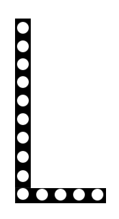
 Design with 11PIN Header (for KCX) in Cirkit Designer
Introduction
The 11PIN Header (for KCX) is a connector with 11 pins designed specifically for interfacing with KCX modules. It provides a reliable and secure electrical connection, making it an essential component in circuit designs that utilize KCX modules. This header is commonly used in audio modules, Bluetooth communication modules, and other embedded systems requiring a compact and efficient connection interface.
Explore Projects Built with 11PIN Header (for KCX)
 Open Project in Cirkit Designer
 Open Project in Cirkit Designer
 Open Project in Cirkit Designer
 Open Project in Cirkit Designer
Explore Projects Built with 11PIN Header (for KCX)
Open Project in Cirkit DesignerOpen Project in Cirkit DesignerOpen Project in Cirkit DesignerOpen Project in Cirkit DesignerCommon Applications
- Interfacing with KCX Bluetooth audio modules
- Embedded systems requiring multi-pin connections
- Prototyping and development of audio and communication circuits
- Secure connections in compact PCB designs
Technical Specifications
Key Technical Details
- Number of Pins: 11
- Pin Pitch: 2.54 mm (standard spacing)
- Rated Voltage: 250V AC/DC
- Rated Current: 3A per pin
- Operating Temperature: -40°C to +105°C
- Material: High-temperature thermoplastic housing with gold-plated pins for durability and low resistance
- Mounting Type: Through-hole or surface-mount, depending on the variant
Pin Configuration and Descriptions
The 11PIN Header (for KCX) typically follows the pinout configuration of the KCX module it is designed to interface with. Below is a general example of the pin configuration:
| Pin Number | Label | Description |
|---|---|---|
| 1 | VCC | Power supply input (typically 3.3V or 5V) |
| 2 | GND | Ground connection |
| 3 | RXD | UART Receive Data |
| 4 | TXD | UART Transmit Data |
| 5 | KEY | Control pin for module configuration |
| 6 | STATE | Module status output |
| 7 | AUDIO_L | Left audio channel output |
| 8 | AUDIO_R | Right audio channel output |
| 9 | MIC+ | Microphone positive input |
| 10 | MIC- | Microphone negative input |
| 11 | NC (or GPIO) | Not connected or general-purpose I/O (varies) |
Note: The exact pinout may vary depending on the specific KCX module. Always refer to the module's datasheet for precise details.
Usage Instructions
How to Use the 11PIN Header in a Circuit
Soldering the Header:
- Align the 11PIN Header with the corresponding holes on the PCB.
- Solder each pin securely to ensure a reliable connection.
- Use a soldering iron with a fine tip for precision, especially in compact designs.
Connecting to a KCX Module:
- Insert the KCX module into the header, ensuring proper alignment of pins.
- Verify that the pin labels on the header match the corresponding pins on the module.
Powering the Module:
- Provide the appropriate voltage (e.g., 3.3V or 5V) to the VCC pin.
- Connect the GND pin to the circuit's ground.
Interfacing with a Microcontroller:
- Connect the RXD and TXD pins to the UART pins of the microcontroller for serial communication.
- Use the KEY pin to configure the module if required.
Audio Connections:
- Connect AUDIO_L and AUDIO_R to the left and right audio output channels, respectively.
- If using a microphone, connect MIC+ and MIC- to the corresponding microphone inputs.
Important Considerations
- Pin Alignment: Ensure the KCX module is correctly aligned with the header to avoid damage.
- Voltage Levels: Verify the voltage requirements of the KCX module to prevent overvoltage or undervoltage issues.
- Soldering Precautions: Avoid excessive heat during soldering to prevent damage to the header or PCB.
Example: Connecting to an Arduino UNO
Below is an example of how to connect the 11PIN Header (for KCX) to an Arduino UNO for UART communication:
// Example code for interfacing a KCX module with Arduino UNO
// Ensure the RXD and TXD pins are connected correctly to the Arduino

#include <SoftwareSerial.h>

// Define RX and TX pins for SoftwareSerial
SoftwareSerial kcxSerial(10, 11); // RX = Pin 10, TX = Pin 11

void setup() {
  Serial.begin(9600); // Initialize hardware serial for debugging
  kcxSerial.begin(9600); // Initialize software serial for KCX module

  Serial.println("KCX Module Communication Started");
}

void loop() {
  // Check if data is available from the KCX module
  if (kcxSerial.available()) {
    String data = kcxSerial.readString(); // Read data from KCX module
    Serial.print("Received from KCX: ");
    Serial.println(data); // Print data to Serial Monitor
  }

  // Example: Send data to KCX module
  if (Serial.available()) {
    String command = Serial.readString(); // Read user input from Serial Monitor
    kcxSerial.println(command); // Send command to KCX module
  }
}
Note: Replace
10and11with the appropriate pins on your Arduino if needed. Ensure the baud rate matches the KCX module's default settings.
Troubleshooting and FAQs
Common Issues
No Communication with KCX Module:
- Cause: Incorrect RXD and TXD connections.
- Solution: Swap the RXD and TXD connections between the header and the microcontroller.
Module Not Powering On:
- Cause: Incorrect voltage or loose connections.
- Solution: Verify the VCC and GND connections and ensure the correct voltage is supplied.
Audio Output Issues:
- Cause: Misaligned or loose connections on AUDIO_L and AUDIO_R pins.
- Solution: Check the audio connections and ensure proper soldering.
Microphone Not Working:
- Cause: MIC+ and MIC- pins not connected properly.
- Solution: Verify the microphone connections and ensure compatibility with the KCX module.
FAQs
Q: Can I use this header with modules other than KCX?
A: Yes, as long as the pinout matches the requirements of the other module.Q: What tools are recommended for soldering this header?
A: Use a fine-tip soldering iron and lead-free solder for best results.Q: Is the header compatible with breadboards?
A: Yes, the 2.54 mm pin pitch makes it compatible with standard breadboards.Q: Can I use this header for high-current applications?
A: The header is rated for 3A per pin. Ensure your application does not exceed this limit.
By following this documentation, you can effectively integrate the 11PIN Header (for KCX) into your projects and troubleshoot common issues with ease.