
How to Use 1 Channel Relay 5V: Examples, Pinouts, and Specs
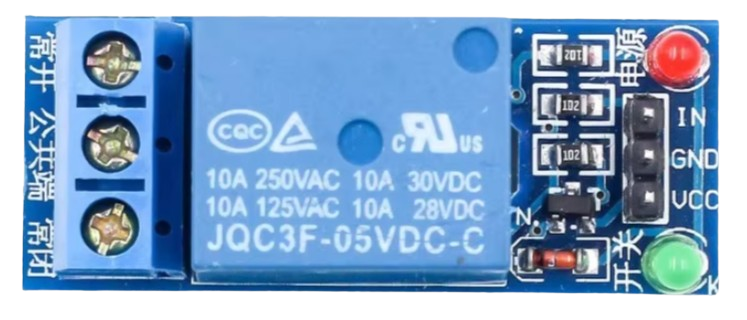
 Design with 1 Channel Relay 5V in Cirkit Designer
Introduction
The 1 Channel Relay 5V is an electromechanical switch module that allows a low voltage control signal (e.g., from a microcontroller) to control a higher voltage circuit. This relay module is widely used in automation, home appliances, and industrial control systems. It is ideal for switching devices such as lights, fans, motors, and other high-power loads.
Explore Projects Built with 1 Channel Relay 5V
 Open Project in Cirkit Designer
 Open Project in Cirkit Designer
 Open Project in Cirkit Designer
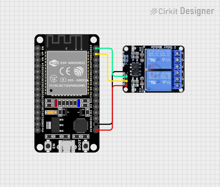 Open Project in Cirkit Designer
Explore Projects Built with 1 Channel Relay 5V
Open Project in Cirkit DesignerOpen Project in Cirkit DesignerOpen Project in Cirkit DesignerOpen Project in Cirkit DesignerCommon Applications and Use Cases
- Home automation systems (e.g., controlling lights or appliances)
- Industrial control systems
- Motor control
- IoT projects
- Smart home devices
- Security systems (e.g., activating alarms or locks)
Technical Specifications
The following table outlines the key technical details of the 1 Channel Relay 5V module:
| Parameter | Specification |
|---|---|
| Operating Voltage | 5V DC |
| Trigger Voltage | 3.3V to 5V DC |
| Maximum Load Voltage | 250V AC / 30V DC |
| Maximum Load Current | 10A |
| Relay Type | SPDT (Single Pole Double Throw) |
| Isolation | Optocoupler isolation for signal input |
| Dimensions | ~50mm x 26mm x 18mm |
| Weight | ~15g |
Pin Configuration and Descriptions
The 1 Channel Relay 5V module has the following pins and terminals:
Input Pins
| Pin Name | Description |
|---|---|
| VCC | Connect to 5V DC power supply. |
| GND | Connect to ground (0V). |
| IN | Control signal input. A HIGH signal activates the relay, and a LOW signal |
| deactivates it. |
Output Terminals
| Terminal Name | Description |
|---|---|
| COM | Common terminal. Connect to one side of the load. |
| NO | Normally Open terminal. Connect to the other side of the load if you |
| want the circuit to close when the relay is activated. | |
| NC | Normally Closed terminal. Connect to the other side of the load if |
| you want the circuit to open when the relay is activated. |
Usage Instructions
How to Use the Component in a Circuit
- Power the Relay Module: Connect the VCC pin to a 5V DC power supply and the GND pin to ground.
- Connect the Control Signal: Connect the IN pin to a microcontroller (e.g., Arduino UNO) or any other control circuit capable of providing a 3.3V to 5V signal.
- Connect the Load:
- Identify whether you want the load to be normally open (NO) or normally closed (NC).
- Connect one side of the load to the COM terminal.
- Connect the other side of the load to either the NO or NC terminal, depending on your desired behavior.
- Control the Relay: Send a HIGH signal to the IN pin to activate the relay and close the NO circuit (or open the NC circuit). Send a LOW signal to deactivate the relay.
Important Considerations and Best Practices
- Isolation: Ensure proper isolation between the low voltage control circuit and the high voltage load to prevent damage or hazards.
- Power Ratings: Do not exceed the maximum voltage (250V AC / 30V DC) or current (10A) ratings of the relay.
- Flyback Diode: If controlling an inductive load (e.g., a motor), use a flyback diode across the load to protect the relay from voltage spikes.
- Signal Stability: Avoid sending noisy or unstable signals to the IN pin, as this may cause erratic relay behavior.
Example: Connecting to an Arduino UNO
Below is an example of how to control the 1 Channel Relay 5V module using an Arduino UNO:
Circuit Connections
- Connect the relay module's VCC pin to the Arduino's 5V pin.
- Connect the relay module's GND pin to the Arduino's GND pin.
- Connect the relay module's IN pin to Arduino digital pin 7.
- Connect the load (e.g., a light bulb) to the COM and NO terminals of the relay.
Arduino Code
// Define the relay control pin
const int relayPin = 7;

void setup() {
  // Set the relay pin as an output
  pinMode(relayPin, OUTPUT);

  // Ensure the relay is off at startup
  digitalWrite(relayPin, LOW);
}

void loop() {
  // Turn the relay on (activate the load)
  digitalWrite(relayPin, HIGH);
  delay(5000); // Keep the relay on for 5 seconds

  // Turn the relay off (deactivate the load)
  digitalWrite(relayPin, LOW);
  delay(5000); // Keep the relay off for 5 seconds
}
Troubleshooting and FAQs
Common Issues and Solutions
Relay Not Activating:
- Ensure the VCC and GND pins are properly connected to a 5V power supply.
- Verify that the IN pin is receiving a HIGH signal (3.3V to 5V).
- Check for loose or faulty connections.
Load Not Switching:
- Confirm that the load is properly connected to the COM and NO/NC terminals.
- Ensure the load does not exceed the relay's voltage or current ratings.
- Check for a blown fuse or damaged load.
Relay Clicking Continuously:
- This may be caused by a noisy or unstable control signal. Use a pull-down resistor on the IN pin to stabilize the signal.
- Verify that the power supply is stable and not fluctuating.
Burnt Smell or Overheating:
- Disconnect the relay immediately and inspect for damage.
- Ensure the load does not exceed the relay's power ratings.
- Check for short circuits in the wiring.
FAQs
Q: Can I use the relay module with a 3.3V microcontroller?
A: Yes, the relay module can be triggered with a 3.3V control signal, but ensure the VCC pin is still powered with 5V.
Q: Is the relay module safe for high voltage applications?
A: Yes, the relay is designed for high voltage applications up to 250V AC, but proper isolation and safety precautions must be followed.
Q: Can I control multiple relays with one Arduino?
A: Yes, you can control multiple relays by connecting each relay's IN pin to a separate digital pin on the Arduino.
Q: Why is the relay making a buzzing noise?
A: This could be due to insufficient power supply or an unstable control signal. Verify the power source and signal integrity.