Cirkit Designer Logo
Cirkit Designer
Your all-in-one circuit design IDE
Home / 
Component Documentation

How to Use RTC DS3231: Examples, Pinouts, and Specs

Image of RTC DS3231
Cirkit Designer LogoDesign with RTC DS3231 in Cirkit Designer

Introduction

The Real-Time Clock (RTC) DS3231 is a low-cost, extremely accurate I2C real-time clock (RTC) with an integrated temperature-compensated crystal oscillator (TCXO) and crystal. The device incorporates a battery input, and maintains accurate timekeeping when the main power to the device is interrupted. The integration of the crystal resonator enhances the long-term accuracy of the device and reduces the piece-part count in a manufacturing line. Common applications of the DS3231 include timekeeping for embedded systems, data loggers, time stamps, and other time-critical applications.

Explore Projects Built with RTC DS3231

Use Cirkit Designer to design, explore, and prototype these projects online. Some projects support real-time simulation. Click "Open Project" to start designing instantly!
ESP32-Based Real-Time Clock Synchronization
Image of DS3231: A project utilizing RTC DS3231 in a practical application
This circuit connects an ESP32 Devkit V1 microcontroller with an RTC DS3231 real-time clock module. The ESP32 provides power to the RTC and communicates with it via I2C, with D21 and D22 serving as the data (SDA) and clock (SCL) lines, respectively. The common ground (GND) ensures a reference point for the voltages, and the 3V3 pin from the ESP32 powers the RTC module.
Cirkit Designer LogoOpen Project in Cirkit Designer
ESP32-Based Real-Time Clock Synchronization
Image of RTC: A project utilizing RTC DS3231 in a practical application
This circuit connects an ESP32 microcontroller to a DS3231 Real Time Clock (RTC) module. The ESP32's Vin and GND pins are connected to the VCC and GND pins of the DS3231, providing power to the RTC. The SCL and SDA pins of the DS3231 are connected to the D22 and D21 pins of the ESP32, respectively, enabling I2C communication between the microcontroller and the RTC module.
Cirkit Designer LogoOpen Project in Cirkit Designer
Arduino UNO with RTC DS3231 Timekeeping
Image of RTC: A project utilizing RTC DS3231 in a practical application
This circuit connects an Arduino UNO microcontroller with a DS3231 Real Time Clock (RTC) module. The Arduino provides 5V power and ground to the RTC and communicates with it via the I2C protocol using the A4 (SDA) and A5 (SCL) pins. The embedded code on the Arduino is used to initialize the RTC, check for power loss, set the current time if needed, and periodically read and print the current time to the serial monitor.
Cirkit Designer LogoOpen Project in Cirkit Designer
Arduino Nano Based Real-Time Clock Display with TM1637
Image of 7segmant: A project utilizing RTC DS3231 in a practical application
This circuit features an Arduino Nano interfacing with a DS3231 Real-Time Clock for timekeeping and a TM1637 display module for visual output. The Arduino facilitates I2C communication with the RTC and controls the display using digital IO, serving as the central processing unit for a digital clock or timer application.
Cirkit Designer LogoOpen Project in Cirkit Designer

Explore Projects Built with RTC DS3231

Use Cirkit Designer to design, explore, and prototype these projects online. Some projects support real-time simulation. Click "Open Project" to start designing instantly!
Image of DS3231: A project utilizing RTC DS3231 in a practical application
ESP32-Based Real-Time Clock Synchronization
This circuit connects an ESP32 Devkit V1 microcontroller with an RTC DS3231 real-time clock module. The ESP32 provides power to the RTC and communicates with it via I2C, with D21 and D22 serving as the data (SDA) and clock (SCL) lines, respectively. The common ground (GND) ensures a reference point for the voltages, and the 3V3 pin from the ESP32 powers the RTC module.
Cirkit Designer LogoOpen Project in Cirkit Designer
Image of RTC: A project utilizing RTC DS3231 in a practical application
ESP32-Based Real-Time Clock Synchronization
This circuit connects an ESP32 microcontroller to a DS3231 Real Time Clock (RTC) module. The ESP32's Vin and GND pins are connected to the VCC and GND pins of the DS3231, providing power to the RTC. The SCL and SDA pins of the DS3231 are connected to the D22 and D21 pins of the ESP32, respectively, enabling I2C communication between the microcontroller and the RTC module.
Cirkit Designer LogoOpen Project in Cirkit Designer
Image of RTC: A project utilizing RTC DS3231 in a practical application
Arduino UNO with RTC DS3231 Timekeeping
This circuit connects an Arduino UNO microcontroller with a DS3231 Real Time Clock (RTC) module. The Arduino provides 5V power and ground to the RTC and communicates with it via the I2C protocol using the A4 (SDA) and A5 (SCL) pins. The embedded code on the Arduino is used to initialize the RTC, check for power loss, set the current time if needed, and periodically read and print the current time to the serial monitor.
Cirkit Designer LogoOpen Project in Cirkit Designer
Image of 7segmant: A project utilizing RTC DS3231 in a practical application
Arduino Nano Based Real-Time Clock Display with TM1637
This circuit features an Arduino Nano interfacing with a DS3231 Real-Time Clock for timekeeping and a TM1637 display module for visual output. The Arduino facilitates I2C communication with the RTC and controls the display using digital IO, serving as the central processing unit for a digital clock or timer application.
Cirkit Designer LogoOpen Project in Cirkit Designer

Technical Specifications

Key Technical Details

  • Time Accuracy: ±2ppm from 0°C to +40°C
  • Battery Backup: Yes (typically a CR2032 coin cell battery)
  • Operating Voltage: 2.3V to 5.5V
  • Operating Temperature: -40°C to +85°C
  • Interface: I2C Serial
  • Memory: 236 bytes of NV SRAM

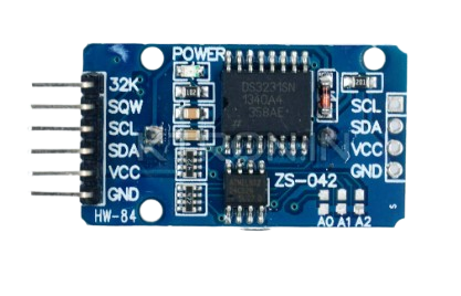
Pin Configuration and Descriptions

Pin Number Name Description
1 32K 32kHz Output
2 SQW Square Wave/Interrupt Output
3 SCL Serial Clock Input
4 SDA Serial Data Input/Output
5 VCC Supply Voltage
6 GND Ground
7 BAT Battery Input for Any Standard 3V Lithium Cell or Other Energy Source

Usage Instructions

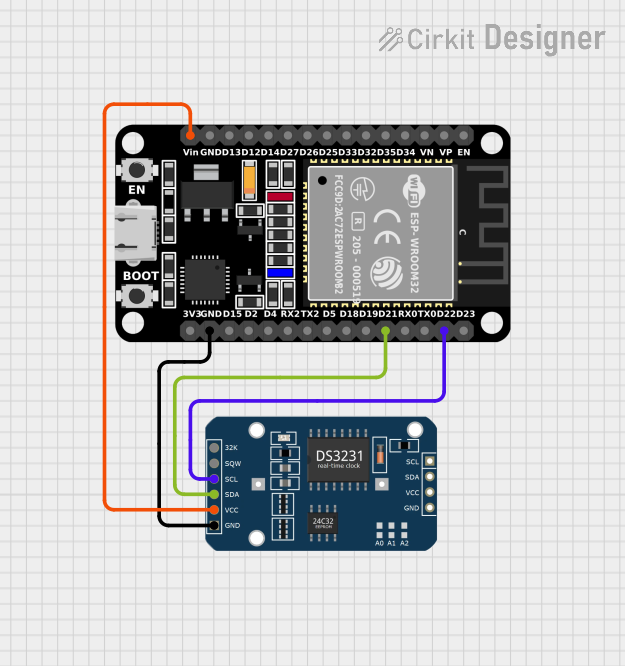
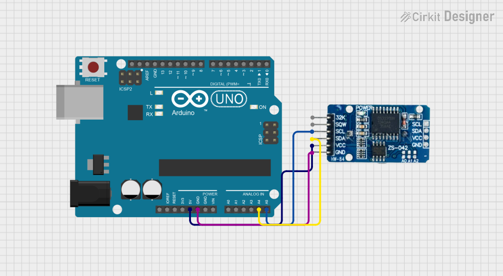
Interfacing with a Circuit

To use the DS3231 in a circuit:

  1. Connect VCC to a 3.3V or 5V power supply (depending on your system requirements).
  2. Connect GND to the ground of your power supply.
  3. Connect SDA and SCL to your microcontroller's I2C data and clock lines respectively.
  4. Optionally, connect the 32K pin to an input if you require a 32kHz square wave.
  5. Optionally, connect the SQW pin to an interrupt input on your microcontroller if you need a square wave or alarm interrupt.

Important Considerations and Best Practices

  • Ensure that the I2C bus lines (SDA and SCL) have pull-up resistors, typically 4.7kΩ to 10kΩ.
  • Keep the battery connected if you want the RTC to keep time when the main power is off.
  • Avoid placing heat-generating components near the DS3231 to prevent temperature-induced inaccuracies.
  • Use proper decoupling capacitors close to the VCC pin to filter out noise.

Example Code for Arduino UNO

#include <Wire.h>
#include <RTClib.h>

RTC_DS3231 rtc;

void setup() {
  Serial.begin(9600);
  
  // Check if the RTC is connected correctly
  if (!rtc.begin()) {
    Serial.println("Couldn't find RTC");
    while (1);
  }

  // Check if the RTC lost power and if so, set the time
  if (rtc.lostPower()) {
    Serial.println("RTC lost power, let's set the time!");
    // The following line sets the RTC to the date & time this sketch was compiled
    rtc.adjust(DateTime(F(__DATE__), F(__TIME__)));
  }
}

void loop() {
  DateTime now = rtc.now();
  
  Serial.print(now.year(), DEC);
  Serial.print('/');
  Serial.print(now.month(), DEC);
  Serial.print('/');
  Serial.print(now.day(), DEC);
  Serial.print(" ");
  Serial.print(now.hour(), DEC);
  Serial.print(':');
  Serial.print(now.minute(), DEC);
  Serial.print(':');
  Serial.print(now.second(), DEC);
  Serial.println();
  
  delay(1000);
}

Troubleshooting and FAQs

Common Issues

  • Time Not Accurate: Ensure the battery is installed correctly and has charge.
  • I2C Communication Failure: Check the pull-up resistors on the SDA and SCL lines.
  • Device Not Found: Verify wiring, ensure correct I2C address is used, and check for soldering issues.

Solutions and Tips

  • If the time drifts significantly, consider replacing the battery.
  • Use the rtc.lostPower() function to check if the RTC has lost power and to set the time again if necessary.
  • For long cable runs, consider using lower value pull-up resistors to maintain signal integrity.

FAQs

Q: How do I set the alarm function on the DS3231?

A: The DS3231 has two alarm functions that can be programmed using the RTClib library. Refer to the library documentation for alarm setup instructions.

Q: Can the DS3231 be used in battery-only mode?

A: Yes, the DS3231 can be powered solely by the battery, but VCC must be connected to a high-impedance state to prevent leakage current from the main supply.

Q: What is the purpose of the 32K pin?

A: The 32K pin outputs a 32kHz square wave that can be used to drive timing circuits or as a clock reference for other devices.