How to Use bolt iot: Examples, Pinouts, and Specs
Introduction
The Bolt IoT platform, manufactured by Bolt IoT (Part ID: boltiot), is a versatile and user-friendly solution for creating and managing Internet of Things (IoT) applications. It provides developers with tools for seamless device connectivity, efficient data management, and real-time analytics. The Bolt IoT platform is designed to simplify the development process, making it accessible to both beginners and experienced IoT developers.
Explore Projects Built with bolt iot
Explore Projects Built with bolt iot
Common Applications and Use Cases
- Home Automation: Control and monitor home appliances remotely.
- Industrial IoT: Track and manage industrial equipment and processes.
- Smart Agriculture: Monitor environmental parameters like temperature, humidity, and soil moisture.
- Health Monitoring: Collect and analyze health-related data from wearable devices.
- Educational Projects: Ideal for students and hobbyists to learn IoT concepts.
Technical Specifications
Key Technical Details
- Microcontroller: ESP8266 Wi-Fi module
- Connectivity: 2.4 GHz Wi-Fi
- Input Voltage: 5V (via Micro-USB)
- Power Consumption: ~200 mA (active mode)
- Digital I/O Pins: 5 (3.3V logic level)
- Analog Input Pins: 1 (10-bit resolution)
- Cloud Platform: Bolt Cloud for data visualization and device management
- Programming Languages: Python, JavaScript, HTML, and Bolt API
- Dimensions: 6.5 cm x 2.5 cm x 1.2 cm
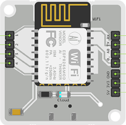
Pin Configuration and Descriptions
The Bolt IoT module has a simple pinout for easy integration into circuits. Below is the pin configuration:
| Pin Name | Type | Description |
|---|---|---|
| 5V | Power Input | Connect to a 5V power source (via Micro-USB or external power supply). |
| GND | Ground | Common ground for the circuit. |
| A0 | Analog Input | Single analog input pin (0-1V range, 10-bit resolution). |
| GPIO 0 | Digital I/O | General-purpose digital input/output pin. |
| GPIO 1 | Digital I/O | General-purpose digital input/output pin. |
| GPIO 2 | Digital I/O | General-purpose digital input/output pin. |
| GPIO 3 | Digital I/O | General-purpose digital input/output pin. |
| GPIO 4 | Digital I/O | General-purpose digital input/output pin. |
Usage Instructions
How to Use the Bolt IoT Module in a Circuit
- Power the Module: Connect the Bolt IoT module to a 5V power source using a Micro-USB cable or an external power supply.
- Connect Sensors/Actuators: Attach sensors to the analog (A0) or digital (GPIO) pins as required by your application.
- Set Up Wi-Fi: Use the Bolt IoT mobile app to configure the module's Wi-Fi credentials for internet connectivity.
- Access the Cloud: Log in to the Bolt Cloud platform to monitor data, create dashboards, and control devices.
- Write Code: Use the Bolt API or supported programming languages (e.g., Python) to develop your IoT application.
Important Considerations and Best Practices
- Voltage Levels: Ensure that the input voltage to the analog pin (A0) does not exceed 1V. Use a voltage divider if necessary.
- Wi-Fi Signal Strength: Place the module in an area with a strong Wi-Fi signal to ensure reliable connectivity.
- Power Supply: Use a stable 5V power source to avoid unexpected resets or malfunctions.
- GPIO Pin Current: Do not exceed 12 mA per GPIO pin to prevent damage to the module.
- Firmware Updates: Regularly update the module's firmware via the Bolt Cloud to access new features and security patches.
Example: Connecting Bolt IoT to an Arduino UNO
The Bolt IoT module can be used with an Arduino UNO for advanced IoT applications. Below is an example of interfacing the module with an Arduino to send temperature data to the Bolt Cloud.
Circuit Diagram
- Connect the Bolt IoT module's GND to the Arduino's GND.
- Connect the Bolt IoT module's 5V to the Arduino's 5V.
- Connect a temperature sensor (e.g., LM35) to the Arduino's analog pin (A0).
Arduino Code
#include <BoltIoT-Arduino-Helper.h>

// Define the analog pin connected to the temperature sensor
const int tempSensorPin = A0;

void setup() {
  // Initialize serial communication
  Serial.begin(9600);

  // Initialize Bolt IoT communication
  boltiot.begin(Serial);
}

void loop() {
  // Read the temperature sensor value
  int sensorValue = analogRead(tempSensorPin);

  // Convert the sensor value to temperature in Celsius
  float temperature = (sensorValue * 5.0 / 1023.0) * 100;

  // Send the temperature data to the Bolt Cloud
  boltiot.send("temperature", temperature);

  // Wait for 10 seconds before sending the next reading
  delay(10000);
}
Troubleshooting and FAQs
Common Issues and Solutions
Module Not Connecting to Wi-Fi
- Solution: Ensure the Wi-Fi credentials are entered correctly in the Bolt IoT app. Check that the Wi-Fi network operates on the 2.4 GHz band (not 5 GHz).
No Data on Bolt Cloud
- Solution: Verify that the module is powered on and connected to the internet. Check the code for errors in the data transmission logic.
Analog Readings Are Inaccurate
- Solution: Ensure the input voltage to the A0 pin does not exceed 1V. Use a voltage divider if necessary.
Module Keeps Restarting
- Solution: Check the power supply for stability. Avoid using USB ports with insufficient current output.
Firmware Update Fails
- Solution: Ensure a stable internet connection during the update process. Retry the update via the Bolt Cloud.
FAQs
Q: Can I use the Bolt IoT module without the Bolt Cloud?
A: Yes, you can use the module in standalone mode by programming it directly using the ESP8266 SDK or Arduino IDE.Q: What is the maximum range of the Wi-Fi connectivity?
A: The module can connect to a Wi-Fi network within a range of approximately 30 meters indoors and 100 meters outdoors (line of sight).Q: Can I connect multiple sensors to the Bolt IoT module?
A: Yes, you can connect multiple sensors using the available GPIO and A0 pins. Use external multiplexers if additional pins are required.Q: Is the Bolt IoT module compatible with third-party cloud platforms?
A: Yes, the module can be integrated with platforms like AWS IoT, Google Cloud IoT, and ThingSpeak using APIs.
This documentation provides a comprehensive guide to using the Bolt IoT module effectively. For further assistance, refer to the official Bolt IoT website or community forums.