How to Use Basic Flex Resistor: Examples, Pinouts, and Specs

Introduction
A Basic Flex Resistor, also known as a flex sensor or bend sensor, is an electronic component that adjusts its resistance value as it is bent or flexed. This property makes it an invaluable tool in creating interactive devices that respond to physical manipulation. Common applications include angle sensing in robotics, human motion detection, and input devices for gaming and musical instruments.
Explore Projects Built with Basic Flex Resistor
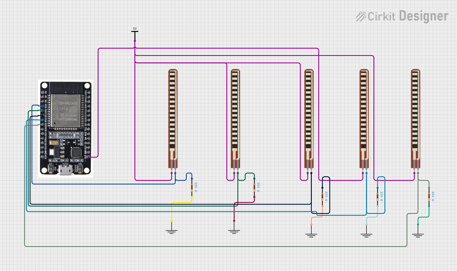
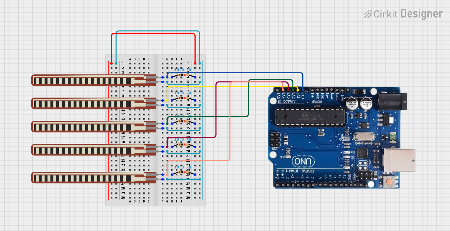
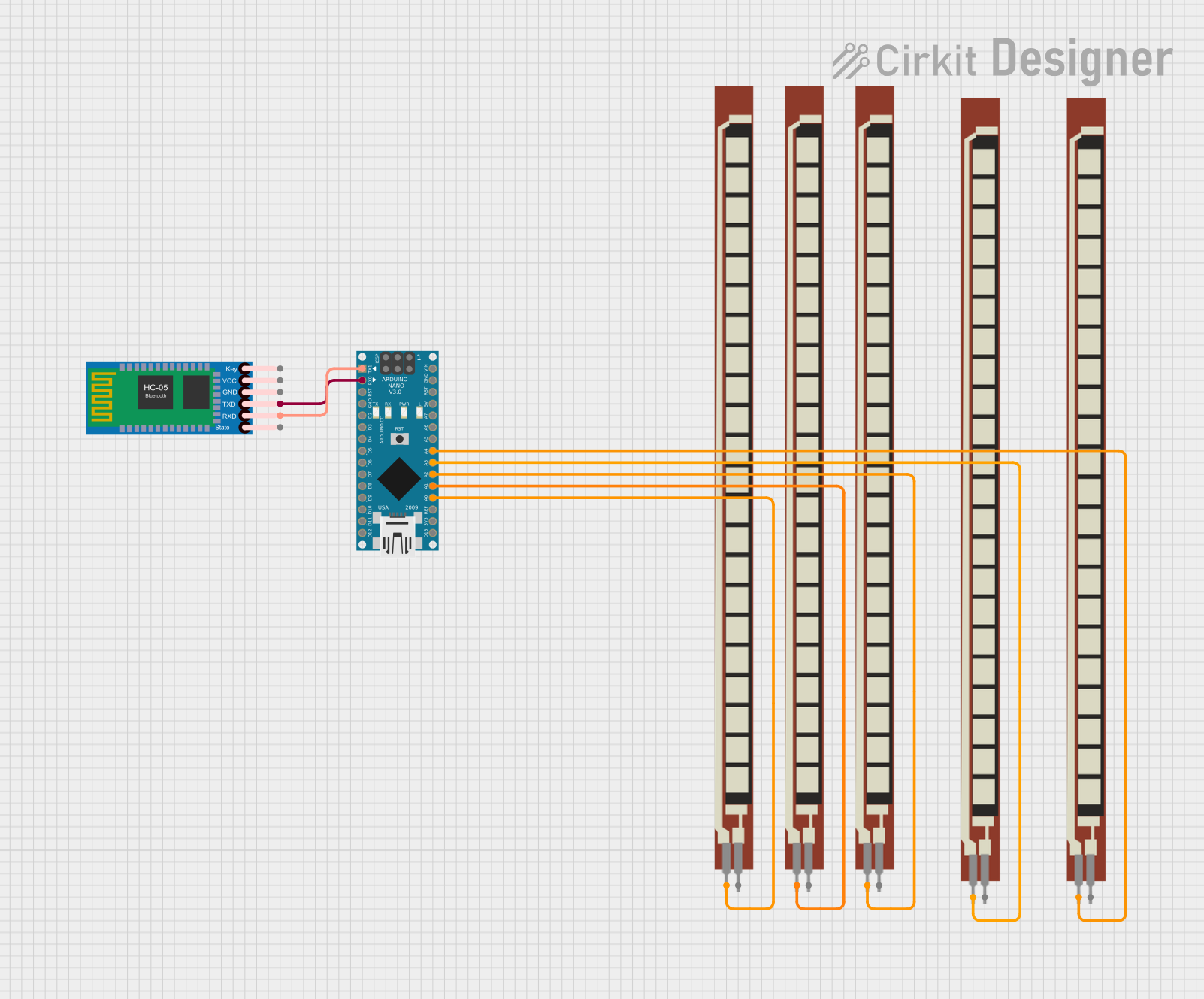
Explore Projects Built with Basic Flex Resistor
Technical Specifications
Key Technical Details
- Resistance Range: Typically 10K to 30K Ohms at rest
- Tolerance: ±30%
- Power Rating: 0.5 Watts (beware of power limits during maximum flex)
- Operating Temperature: -35°C to +80°C
Pin Configuration and Descriptions
| Pin Number | Description |
|---|---|
| 1 | Resistance Output A |
| 2 | Resistance Output B |
Note: The flex resistor is a two-terminal device, with each terminal connected to the ends of the resistive material.
Usage Instructions
Integration into a Circuit
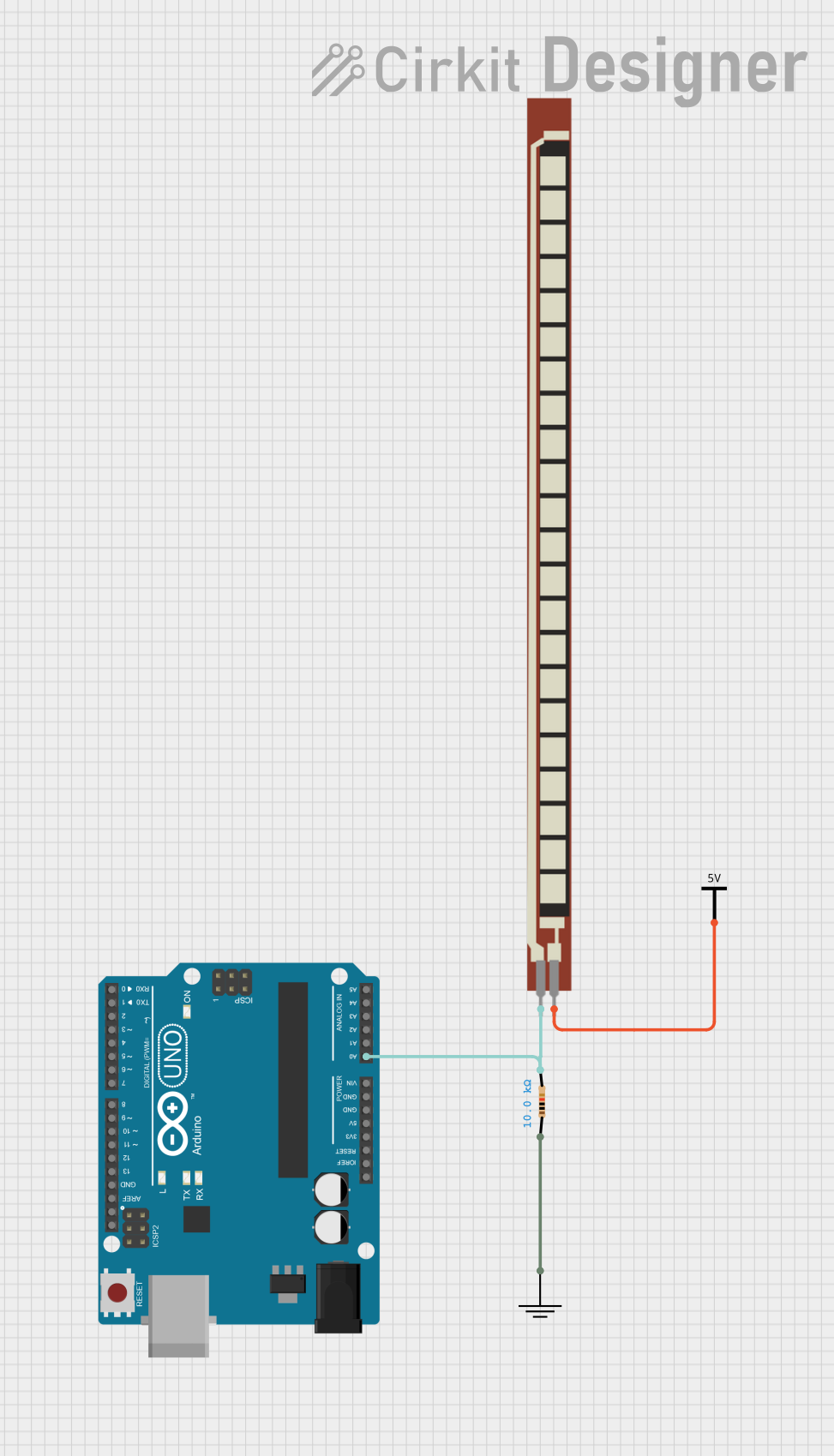
To use a Basic Flex Resistor in a circuit, it is typically placed in series with a static resistor to form a voltage divider. This setup allows the change in resistance due to flexing to be converted into a measurable change in voltage.
Example Circuit
Vcc (5V) ---[Static Resistor]---|---[Flex Resistor]--- GND
                                |
                             Analog Pin
Best Practices
- Avoid sharp bends which may damage the sensor.
- Do not exceed the power rating as it may permanently affect the sensor's performance.
- Ensure the sensor is securely mounted but with enough freedom to bend.
Example Code for Arduino UNO
This example demonstrates how to read the value from a Basic Flex Resistor using an Arduino UNO.
// Define the flex sensor pin
const int flexPin = A0; // Analog input pin

void setup() {
  // Start the serial communication
  Serial.begin(9600);
}

void loop() {
  // Read the ADC value from the flex sensor pin
  int flexValue = analogRead(flexPin);

  // Map the ADC value to a range of angles or positions as needed
  // int angle = map(flexValue, ADC_min, ADC_max, angle_min, angle_max);

  // Print the ADC value to the Serial Monitor
  Serial.println(flexValue);

  // Delay for a bit to avoid spamming the serial output
  delay(250);
}
Note: Replace ADC_min, ADC_max, angle_min, and angle_max with the actual values corresponding to the minimum and maximum readings of the flex sensor and the desired angle range.
Troubleshooting and FAQs
Common Issues
- Inconsistent Readings: Ensure that the flex sensor is not damaged and is connected properly.
- Sensor Not Responding: Check if the static resistor value is appropriate for forming a voltage divider with the flex sensor.
FAQs
Q: Can I use a flex sensor with a microcontroller other than an Arduino? A: Yes, flex sensors are passive components and can be used with any microcontroller that has an ADC.
Q: How do I calibrate the flex sensor? A: Calibrate the sensor by measuring the resistance at known angles and mapping these to the ADC readings.
Q: What is the lifespan of a flex sensor? A: Lifespan varies based on usage, but flex sensors can typically withstand thousands of flex cycles before performance degrades.
Q: Can the flex sensor be cut to size? A: No, cutting the sensor will damage it and alter its resistance properties.
For further assistance, consult the manufacturer's datasheet or contact technical support.