How to Use H-bridge PCB: Examples, Pinouts, and Specs
Introduction
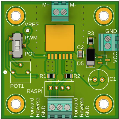
The H-bridge PCB is a printed circuit board designed to control the direction and speed of a DC motor using an H-bridge configuration. This versatile component enables bidirectional control of DC motors, making it an essential tool for robotics, automation, and motorized systems. By manipulating the polarity of the voltage applied to the motor, the H-bridge PCB allows for forward and reverse motion, as well as speed control through pulse-width modulation (PWM).
Explore Projects Built with H-bridge PCB
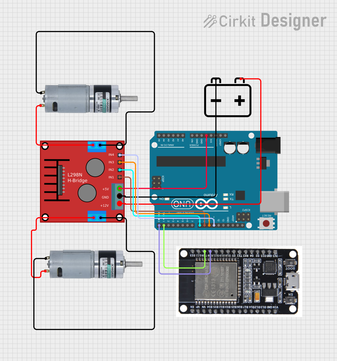
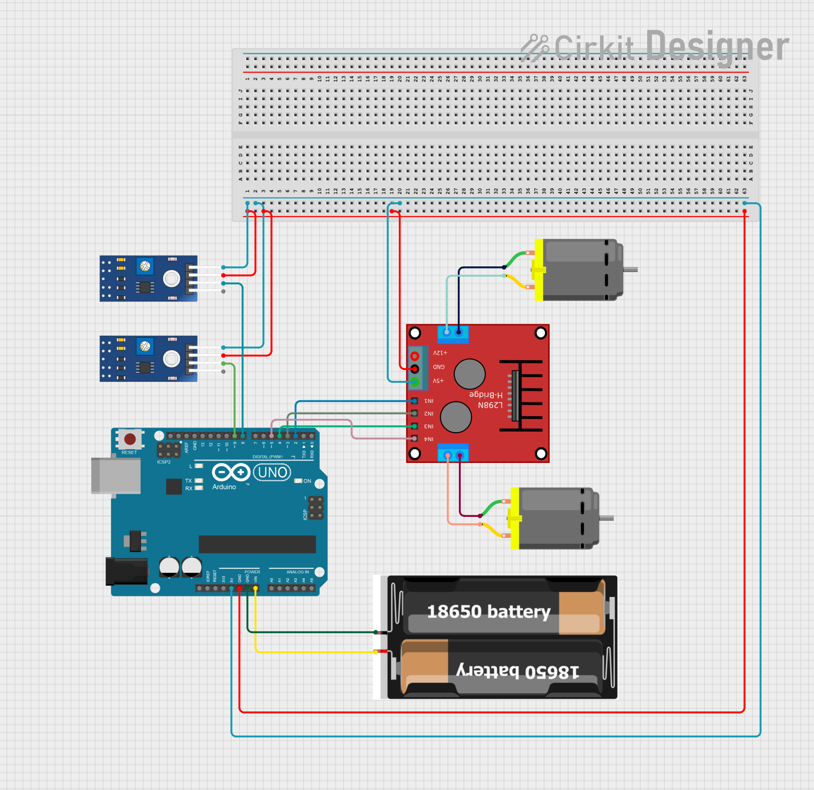
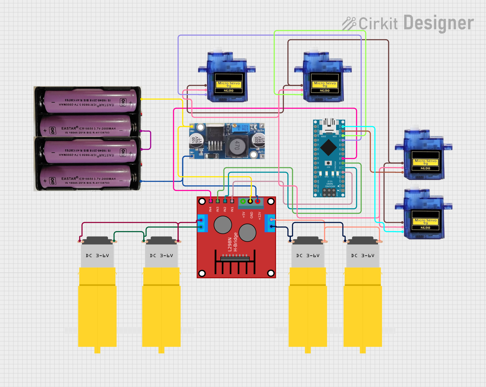
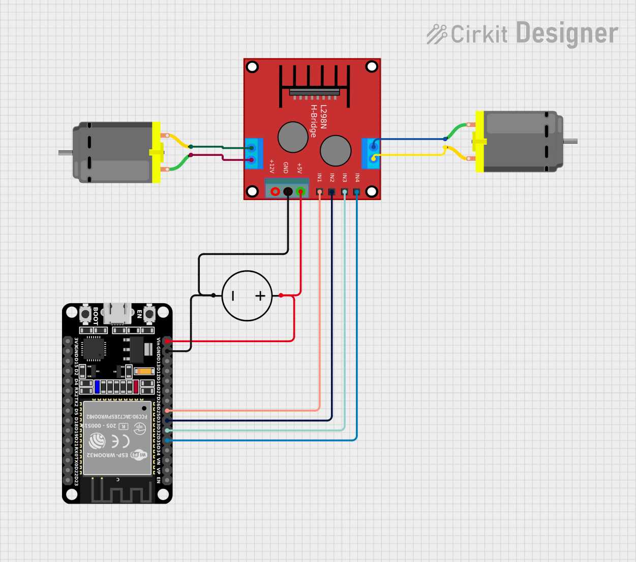
Explore Projects Built with H-bridge PCB
Common Applications and Use Cases
- Robotics: Controlling the movement of robot wheels or arms.
- Automation systems: Operating conveyor belts or actuators.
- Remote-controlled vehicles: Managing motor direction and speed.
- DIY projects: Building motorized systems such as fans, cars, or sliders.
Technical Specifications
The H-bridge PCB is designed to handle a wide range of DC motors and is compatible with microcontrollers like Arduino, Raspberry Pi, and others. Below are the key technical details:
General Specifications
| Parameter | Value |
|---|---|
| Operating Voltage | 5V to 36V |
| Maximum Current | 2A per channel (continuous) |
| Peak Current | 3A per channel (short bursts) |
| Control Logic Voltage | 3.3V or 5V |
| PWM Frequency | Up to 20 kHz |
| Number of Channels | 2 (can control 2 motors) |
| Dimensions | 50mm x 40mm x 15mm |
Pin Configuration and Descriptions
| Pin Name | Description |
|---|---|
| VCC | Power supply for the motors (5V to 36V). |
| GND | Ground connection. |
| IN1 | Input signal to control Motor 1 direction (logic HIGH or LOW). |
| IN2 | Input signal to control Motor 1 direction (logic HIGH or LOW). |
| IN3 | Input signal to control Motor 2 direction (logic HIGH or LOW). |
| IN4 | Input signal to control Motor 2 direction (logic HIGH or LOW). |
| ENA | Enable pin for Motor 1 (connect to PWM for speed control). |
| ENB | Enable pin for Motor 2 (connect to PWM for speed control). |
| OUT1 | Output terminal for Motor 1. |
| OUT2 | Output terminal for Motor 1. |
| OUT3 | Output terminal for Motor 2. |
| OUT4 | Output terminal for Motor 2. |
Usage Instructions
How to Use the H-bridge PCB in a Circuit
- Power Supply: Connect the VCC pin to a power source that matches the voltage requirements of your motor (5V to 36V). Connect the GND pin to the ground of your power source.
- Motor Connections: Attach the motor terminals to the corresponding output pins (OUT1 and OUT2 for Motor 1, OUT3 and OUT4 for Motor 2).
- Control Signals: Connect the IN1, IN2, IN3, and IN4 pins to the digital output pins of your microcontroller. These pins control the direction of the motors.
- Speed Control: Use the ENA and ENB pins for speed control by connecting them to PWM-capable pins on your microcontroller.
- Logic Voltage: Ensure the control logic voltage (3.3V or 5V) matches your microcontroller's output.
Important Considerations and Best Practices
- Heat Dissipation: If operating at high currents, ensure proper heat dissipation by attaching a heatsink or using active cooling.
- Current Limits: Do not exceed the maximum current rating (2A continuous, 3A peak) to avoid damaging the PCB.
- Flyback Diodes: The H-bridge PCB typically includes built-in flyback diodes to protect against voltage spikes. Verify this in the datasheet if using a custom PCB.
- Decoupling Capacitors: Add decoupling capacitors near the power supply pins to reduce noise and stabilize the voltage.
Example Code for Arduino UNO
Below is an example of how to control a DC motor using the H-bridge PCB and an Arduino UNO:
// Define control pins for Motor 1
const int IN1 = 9;  // Direction control pin 1
const int IN2 = 8;  // Direction control pin 2
const int ENA = 10; // PWM pin for speed control

void setup() {
  // Set motor control pins as outputs
  pinMode(IN1, OUTPUT);
  pinMode(IN2, OUTPUT);
  pinMode(ENA, OUTPUT);
}

void loop() {
  // Rotate motor forward at 50% speed
  digitalWrite(IN1, HIGH);  // Set direction
  digitalWrite(IN2, LOW);   // Set direction
  analogWrite(ENA, 128);    // Set speed (0-255)

  delay(2000); // Run motor for 2 seconds

  // Rotate motor backward at 75% speed
  digitalWrite(IN1, LOW);   // Reverse direction
  digitalWrite(IN2, HIGH);  // Reverse direction
  analogWrite(ENA, 192);    // Set speed (0-255)

  delay(2000); // Run motor for 2 seconds

  // Stop the motor
  digitalWrite(IN1, LOW);
  digitalWrite(IN2, LOW);
  analogWrite(ENA, 0);      // Set speed to 0

  delay(2000); // Wait for 2 seconds before repeating
}
Troubleshooting and FAQs
Common Issues and Solutions
Motor Not Spinning:
- Cause: Incorrect wiring or insufficient power supply.
- Solution: Double-check all connections, ensure the power supply matches the motor's voltage, and verify the control signals.
Motor Spins in One Direction Only:
- Cause: One of the direction control pins (IN1, IN2, etc.) is not receiving the correct signal.
- Solution: Test the control pins with a multimeter or logic analyzer to ensure proper signal output.
Overheating:
- Cause: Excessive current draw or insufficient cooling.
- Solution: Reduce the motor load, ensure the current is within the rated limits, and add a heatsink if necessary.
PWM Not Controlling Speed:
- Cause: Incorrect PWM frequency or improper connection to the ENA/ENB pins.
- Solution: Verify the PWM frequency is within the supported range (up to 20 kHz) and ensure the ENA/ENB pins are connected to PWM-capable microcontroller pins.
FAQs
Can I use the H-bridge PCB with a stepper motor? No, the H-bridge PCB is designed for DC motors. Stepper motors require a dedicated stepper motor driver.
What happens if I reverse the power supply polarity? Reversing the polarity can damage the PCB. Always double-check the polarity before powering the circuit.
Can I control two motors independently? Yes, the H-bridge PCB has two channels, allowing independent control of two motors.
Is it compatible with 3.3V logic microcontrollers like ESP32? Yes, the H-bridge PCB supports both 3.3V and 5V logic levels.