How to Use L298N DC RIGHT motor driver: Examples, Pinouts, and Specs
Introduction
The L298N is a dual H-bridge motor driver that enables control of the direction and speed of DC motors. It is capable of driving two motors simultaneously, making it a versatile and widely used component in robotics, automation, and other motor control applications. The module is designed to handle motors with operating voltages between 5V and 35V and can deliver up to 2A of current per channel. Its compact design and ease of use make it a popular choice for hobbyists and professionals alike.
Explore Projects Built with L298N DC RIGHT motor driver
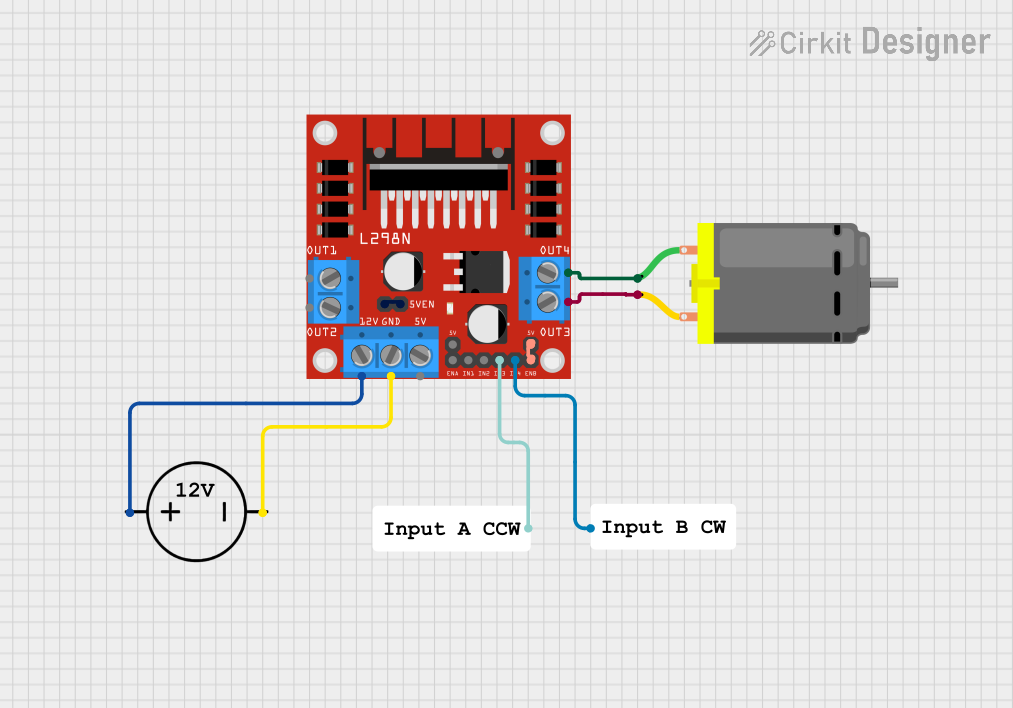
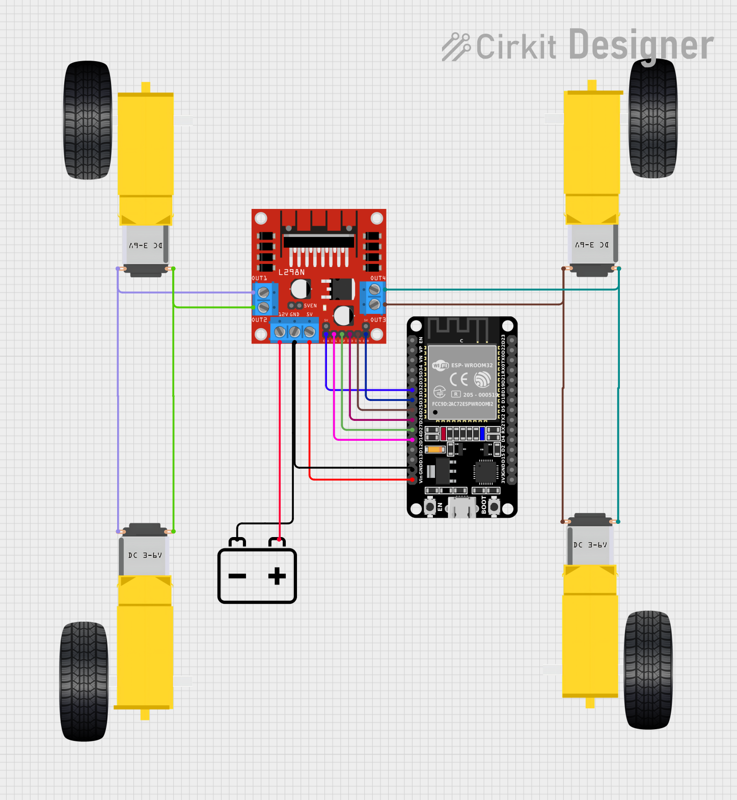


Explore Projects Built with L298N DC RIGHT motor driver
Common Applications and Use Cases
- Robotics: Controlling the movement of robot wheels or arms
- Automation: Driving conveyor belts or automated systems
- Remote-controlled vehicles: Managing motorized wheels or tracks
- DIY projects: Building motorized gadgets or tools
- Educational purposes: Learning about motor control and H-bridge circuits
Technical Specifications
The L298N motor driver module has the following key specifications:
| Parameter | Value |
|---|---|
| Operating Voltage | 5V to 35V |
| Output Current | Up to 2A per channel |
| Logic Voltage | 5V |
| Control Logic Levels | High: 3.5V to 5V, Low: 0V |
| Power Dissipation | 25W (with proper heat sinking) |
| Number of Channels | 2 (dual H-bridge) |
| Dimensions | 43mm x 43mm x 27mm |
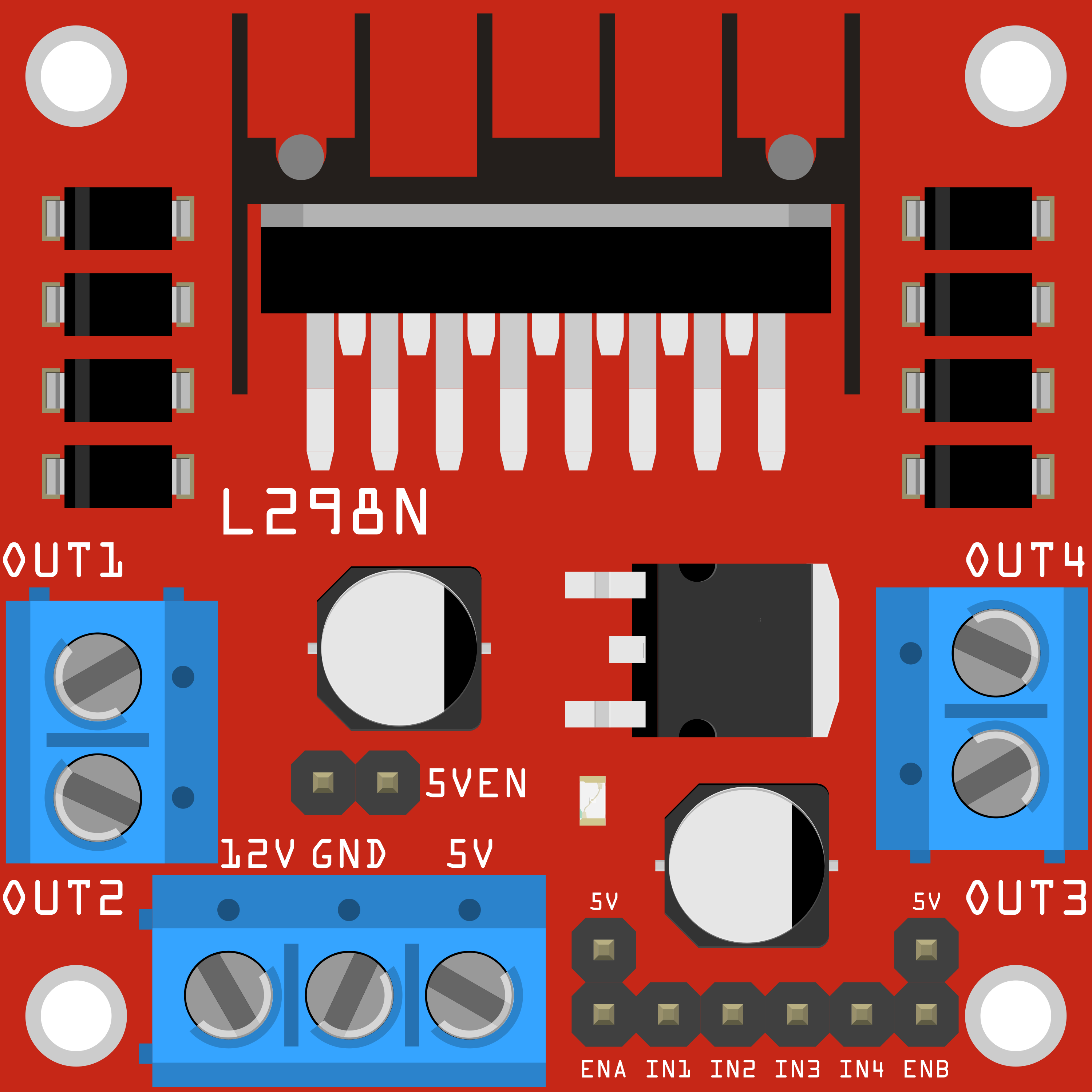
Pin Configuration and Descriptions
The L298N module has several pins and terminals for motor control and power input. Below is a detailed description:
Power and Motor Terminals
| Pin/Terminal | Description |
|---|---|
| VCC | Motor power supply (5V to 35V) |
| GND | Ground connection |
| 5V | Logic power supply (optional, if not using onboard regulator) |
| OUT1 | Output for Motor 1 (connect to one motor terminal) |
| OUT2 | Output for Motor 1 (connect to the other motor terminal) |
| OUT3 | Output for Motor 2 (connect to one motor terminal) |
| OUT4 | Output for Motor 2 (connect to the other motor terminal) |
Control Pins
| Pin | Description |
|---|---|
| ENA | Enable pin for Motor 1 (PWM input for speed control) |
| IN1 | Input 1 for Motor 1 (controls direction) |
| IN2 | Input 2 for Motor 1 (controls direction) |
| ENB | Enable pin for Motor 2 (PWM input for speed control) |
| IN3 | Input 1 for Motor 2 (controls direction) |
| IN4 | Input 2 for Motor 2 (controls direction) |
Usage Instructions
How to Use the L298N in a Circuit
Power Connections:
- Connect the motor power supply to the
VCCterminal (5V to 35V). - Connect the ground of the power supply to the
GNDterminal. - If the motor power supply is above 7V, the onboard 5V regulator can be used to power the logic circuit. In this case, the
5Vpin can be left unconnected or used as a 5V output.
- Connect the motor power supply to the
Motor Connections:
- Connect the terminals of Motor 1 to
OUT1andOUT2. - Connect the terminals of Motor 2 to
OUT3andOUT4.
- Connect the terminals of Motor 1 to
Control Connections:
- Connect the
ENAandENBpins to PWM-capable pins on your microcontroller for speed control. - Connect
IN1,IN2,IN3, andIN4to digital pins on your microcontroller to control motor direction.
- Connect the
Logic Power:
- If the onboard 5V regulator is not used, provide 5V to the
5Vpin from an external source.
- If the onboard 5V regulator is not used, provide 5V to the
Important Considerations and Best Practices
- Use a heat sink on the L298N chip if driving motors with high current to prevent overheating.
- Ensure the motor power supply voltage matches the motor's operating voltage range.
- Use appropriate decoupling capacitors on the power supply to reduce noise and voltage spikes.
- Avoid exceeding the maximum current rating (2A per channel) to prevent damage to the module.
Example: Connecting to an Arduino UNO
Below is an example of how to control a single DC motor using the L298N and an Arduino UNO:
Circuit Connections
- Connect
VCCto a 12V power supply andGNDto the ground. - Connect
OUT1andOUT2to the motor terminals. - Connect
ENAto Arduino pin 9 (PWM pin). - Connect
IN1to Arduino pin 7 andIN2to Arduino pin 8. - Connect the Arduino's
GNDto the L298N'sGND.
Arduino Code
// Define control pins for the L298N motor driver
const int ENA = 9;  // PWM pin for speed control
const int IN1 = 7;  // Direction control pin 1
const int IN2 = 8;  // Direction control pin 2

void setup() {
  // Set control pins as outputs
  pinMode(ENA, OUTPUT);
  pinMode(IN1, OUTPUT);
  pinMode(IN2, OUTPUT);
}

void loop() {
  // Rotate motor forward at 50% speed
  analogWrite(ENA, 128);  // Set speed (0-255)
  digitalWrite(IN1, HIGH); // Set direction
  digitalWrite(IN2, LOW);
  delay(2000); // Run for 2 seconds

  // Rotate motor backward at 75% speed
  analogWrite(ENA, 192);  // Set speed (0-255)
  digitalWrite(IN1, LOW);  // Set direction
  digitalWrite(IN2, HIGH);
  delay(2000); // Run for 2 seconds

  // Stop the motor
  analogWrite(ENA, 0);  // Set speed to 0
  delay(2000); // Wait for 2 seconds
}
Troubleshooting and FAQs
Common Issues and Solutions
Motor Not Running:
- Check all power connections and ensure the motor power supply is within the specified range.
- Verify that the
ENApin is receiving a PWM signal and is not set to 0.
Overheating:
- Ensure a heat sink is installed on the L298N chip if driving high-current motors.
- Reduce the motor load or use motors with lower current requirements.
Erratic Motor Behavior:
- Check for loose connections or poor solder joints.
- Add decoupling capacitors to the power supply to reduce noise.
No Output Voltage on Motor Terminals:
- Verify that the control pins (
IN1,IN2, etc.) are correctly configured in the code. - Ensure the
ENAorENBpin is enabled with a PWM signal.
- Verify that the control pins (
FAQs
Q: Can the L298N drive stepper motors?
A: Yes, the L298N can drive bipolar stepper motors by using both H-bridge channels. However, additional control logic is required.
Q: Can I use the onboard 5V regulator to power my Arduino?
A: Yes, if the motor power supply is above 7V, the onboard 5V regulator can provide power to the Arduino via the 5V pin. However, ensure the current draw does not exceed the regulator's capacity.
Q: What is the maximum motor voltage the L298N can handle?
A: The L298N can handle motor voltages up to 35V. Ensure the motor power supply does not exceed this limit.