
How to Use BLDC Motor Driver: Examples, Pinouts, and Specs
 Design with BLDC Motor Driver in Cirkit Designer
Introduction
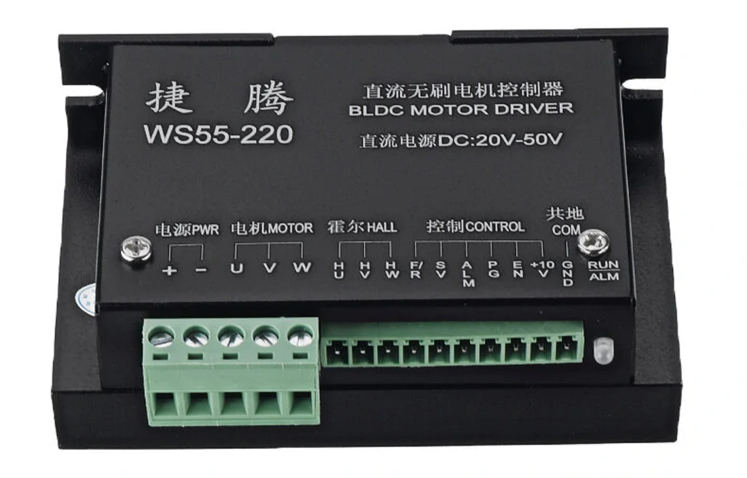
The WS55-220 is a Brushless DC (BLDC) Motor Driver manufactured by NoBrand. It is designed to control the operation of BLDC motors by regulating the voltage and current supplied to the motor windings. This enables precise control of motor speed, direction, and position, making it ideal for a wide range of applications.
Explore Projects Built with BLDC Motor Driver
 Open Project in Cirkit Designer
 Open Project in Cirkit Designer
 Open Project in Cirkit Designer
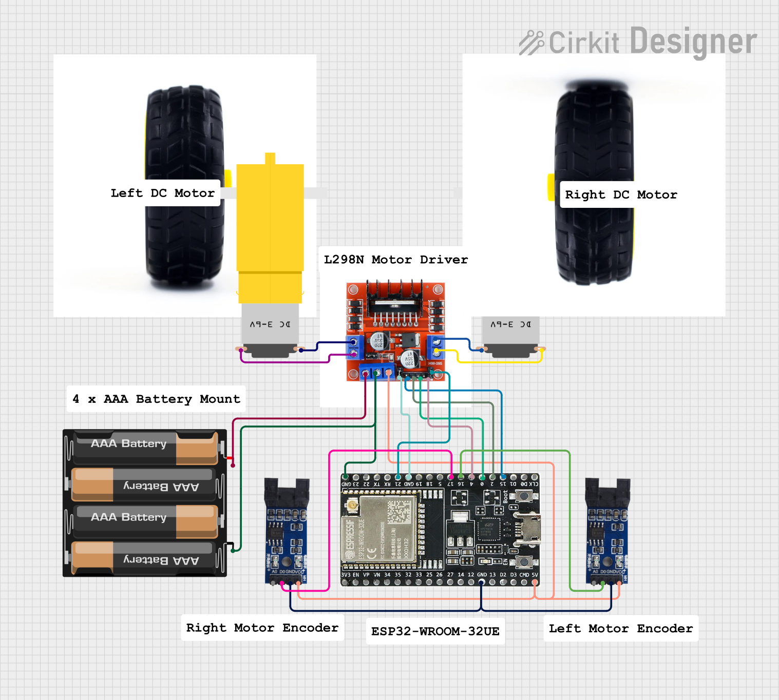 Open Project in Cirkit Designer
Explore Projects Built with BLDC Motor Driver
Open Project in Cirkit DesignerOpen Project in Cirkit DesignerOpen Project in Cirkit DesignerOpen Project in Cirkit DesignerCommon Applications and Use Cases
- Industrial automation and robotics
- Electric vehicles and drones
- HVAC systems (fans and blowers)
- CNC machines and 3D printers
- Home appliances (e.g., washing machines, air conditioners)
Technical Specifications
The following table outlines the key technical details of the WS55-220 BLDC Motor Driver:
| Parameter | Value |
|---|---|
| Input Voltage Range | 20V - 50V DC |
| Maximum Output Current | 15A |
| Rated Power | 500W |
| Control Signal Input | PWM, Analog Voltage (0-5V) |
| Speed Control Range | 0 - 100% |
| Motor Compatibility | 3-phase BLDC motors |
| Operating Temperature | -20°C to 50°C |
| Dimensions | 120mm x 80mm x 40mm |
| Weight | 300g |
Pin Configuration and Descriptions
The WS55-220 features a set of input/output pins for motor control and power connections. The table below describes each pin:
| Pin Name | Type | Description |
|---|---|---|
| VIN+ | Power Input | Positive terminal for DC power supply (20V - 50V). |
| VIN- | Power Input | Negative terminal for DC power supply (ground). |
| U, V, W | Motor Output | Connect to the three-phase windings of the BLDC motor. |
| GND | Signal Ground | Ground reference for control signals. |
| PWM | Control Input | Pulse Width Modulation input for speed control (frequency: 1kHz - 20kHz). |
| VR | Control Input | Analog voltage input (0-5V) for speed control. |
| DIR | Control Input | Direction control input (logic HIGH for forward, LOW for reverse). |
| EN | Control Input | Enable input (logic HIGH to enable the driver, LOW to disable). |
| FG | Output Signal | Frequency generator output for motor speed feedback. |
Usage Instructions
How to Use the WS55-220 in a Circuit
Power Supply Connection:
- Connect a DC power supply (20V - 50V) to the
VIN+andVIN-terminals. - Ensure the power supply can provide sufficient current for the motor's operation.
- Connect a DC power supply (20V - 50V) to the
Motor Connection:
- Connect the three-phase windings of the BLDC motor to the
U,V, andWterminals. - Verify the wiring sequence matches the motor's datasheet to avoid incorrect rotation.
- Connect the three-phase windings of the BLDC motor to the
Control Signal Connection:
- For speed control, connect a PWM signal (1kHz - 20kHz) to the
PWMpin or an analog voltage (0-5V) to theVRpin. - Use the
DIRpin to set the motor's rotation direction (HIGH for forward, LOW for reverse). - Use the
ENpin to enable or disable the driver (HIGH to enable, LOW to disable).
- For speed control, connect a PWM signal (1kHz - 20kHz) to the
Feedback Signal:
- The
FGpin provides a frequency signal proportional to the motor's speed. This can be used for closed-loop control or monitoring.
- The
Important Considerations and Best Practices
- Power Supply: Ensure the power supply voltage and current ratings match the motor's requirements.
- Heat Dissipation: The driver may generate heat during operation. Use a heatsink or active cooling if necessary.
- Wiring: Keep power and signal wires as short as possible to minimize noise and voltage drops.
- Startup: Always start with low speed and gradually increase to avoid sudden torque surges.
- Protection: Use fuses or circuit breakers to protect the driver and motor from overcurrent or short circuits.
Example: Using WS55-220 with Arduino UNO
The following example demonstrates how to control the WS55-220 using an Arduino UNO and a PWM signal:
// Arduino UNO example for controlling WS55-220 BLDC Motor Driver
// Connect the PWM pin of WS55-220 to Arduino pin 9
// Connect the DIR pin of WS55-220 to Arduino pin 8
// Connect the EN pin of WS55-220 to Arduino pin 7

#define PWM_PIN 9  // PWM signal for speed control
#define DIR_PIN 8  // Direction control
#define EN_PIN 7   // Enable control

void setup() {
  pinMode(PWM_PIN, OUTPUT); // Set PWM pin as output
  pinMode(DIR_PIN, OUTPUT); // Set DIR pin as output
  pinMode(EN_PIN, OUTPUT);  // Set EN pin as output

  digitalWrite(EN_PIN, HIGH); // Enable the motor driver
  digitalWrite(DIR_PIN, HIGH); // Set direction to forward
}

void loop() {
  // Gradually increase motor speed
  for (int speed = 0; speed <= 255; speed++) {
    analogWrite(PWM_PIN, speed); // Write PWM signal (0-255)
    delay(20); // Wait for 20ms
  }

  delay(1000); // Run at full speed for 1 second

  // Gradually decrease motor speed
  for (int speed = 255; speed >= 0; speed--) {
    analogWrite(PWM_PIN, speed); // Write PWM signal (0-255)
    delay(20); // Wait for 20ms
  }

  delay(1000); // Wait for 1 second before repeating
}
Troubleshooting and FAQs
Common Issues and Solutions
Motor Does Not Start:
- Verify the power supply voltage and current ratings.
- Check the
ENpin is set to HIGH. - Ensure the motor windings are correctly connected to the
U,V, andWterminals.
Motor Rotates in the Wrong Direction:
- Reverse the logic level of the
DIRpin. - Swap any two motor winding connections (e.g.,
UandV).
- Reverse the logic level of the
Driver Overheats:
- Ensure proper ventilation or use a heatsink.
- Check for excessive current draw from the motor.
No Speed Feedback Signal:
- Verify the
FGpin connection. - Ensure the motor is spinning and the driver is enabled.
- Verify the
FAQs
Q: Can I use a 12V power supply with the WS55-220?
A: No, the WS55-220 requires a minimum input voltage of 20V. Using a lower voltage may damage the driver or prevent it from functioning.
Q: What is the maximum PWM frequency supported?
A: The WS55-220 supports PWM frequencies between 1kHz and 20kHz.
Q: Can I control the motor speed using both PWM and analog voltage simultaneously?
A: No, use either the PWM pin or the VR pin for speed control, but not both at the same time.